Categories
PCB Blog

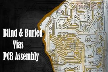
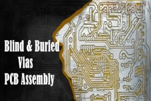
Blind & Buried vias PCB Assembly

In a printed circuit board (PCB), the various chips and components contained therein conduct signals for different functions according to the design requirements. And most of the signals on a printed circuit board are conducted via vias on the board. For high-precision, multi-layer PCBs, the flexible design of different via holes helps to create connections between the multiple layers of the PCB.

In this article we focus on the role of blind and buried vias.

What is Via?

Essentially, vias provide the conduction path for electrical signals to pass from one circuit layer to another. Via holes are plated through-holes in a PCB that can be used to route traces from the surface of the board to the inner and outer layers. Vias are essential in multilayer boards as they create the path for the flow of current between the layers.

Main Types of Vias-Blinds and Buried Vias

There are two main types of vias, depending on their location in the PCB layers – blind and buried vias.

Blind Via Holes

The application of blind vias has arisen in order to increase the space utilisation of the PCB circuit layers. Blind Via Holes are plated holes that connect the outermost circuit of the PCB to the adjacent inner layer and are called Blind Via because the opposite side is not visible.

Buried Holes

It are used to connect any circuit layer within a PCB but are not routed to the outer layer. As the name implies, the buried hole is hidden underneath the board without affecting the surface circuitry and components. Because of the greater demands placed on PCB assembly manufacturers, this process is usually only used for high-density (HDI) circuit boards to allow for better power transmission and to increase the space available for other circuit layers.

Blind vias in PCB assembly

Four types of blind holes are described here

– Photo-defined blind holes. Created by laminating a piece of photosensitive resin onto a core. These through-holes are typically used to create BGA packages.

– Sequentially laminated blind vias. Created by handling a thin piece of laminate. The laminate is drilled, plated and etched. The other side is left as a solid copper sheet.

– Controlled depth blind holes. Created like a through-hole. The drill bit can only penetrate the PCB in a certain way.

– Laser drilled blind holes. Created after all layers in the PCB have been laminated and before the outer layer has been plated and etched. By using a CO₂ laser or an Eximer laser, the outer copper layer is ablated.

Advantages of blind vias

Blind vias help to reduce parasitic capacitance. This is achieved by shortening the length of the through-holes and reducing their diameter. Blind vias are therefore a good way to connect signal lines operating above 4.8 Gb/s.

To Summarize

The main advantages offered by blind and buried vias include

– Meeting the density requirements and constraints of lines and pads in a design without increasing the total number of layers or board size

– Save space and meet extremely tight design tolerances.

– Manage hole-to-pad ratios and limit opportunities for breakthrough.

– Of concern is that they increase the cost of manufacturing the board as well as the cost of testing. However, between the two, buried holes are less costly.

It is important to choose the right electronics contract manufacturing partner with the necessary experience in blind and buried vias. KingPCB has over 10 years’ experience in electronics manufacturing, including PCB manufacturing and PCBA assembly, providing high precision PCB through-hole manufacturing.

Please feel free to contact us by email with any questions, getting an latest quote starts here!

Categories
PCB Blog

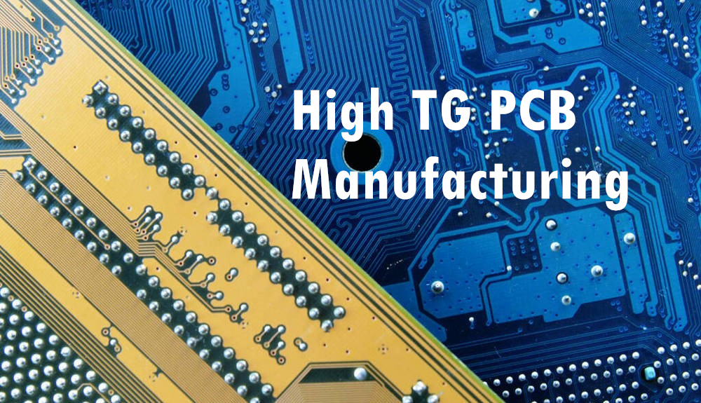
High TG PCB Manufacturing Features and Applications

As we know that, electronic products often work for long periods of time. The heat generated during operation will transfer to other components, ultimately affecting the durability and performance of the product. For some electronic products in applications that are multi-functional but limited by size and weight, high TG PCBs would be a cost-effective way to improve thermal management efficiency.

What is a high TG PCB?

High TG PCBs are boards with a high glass transition temperature. The “TG” is the temperature point at which the material begins to change from a solid to a rubbery state. Generally speaking, high TG is a temperature greater than or equal to 170°C PCB can be called high TG PCB. Medium TG PCB temperature range of 150-160°C. While standard PCBs are usually used for materials with a TG of 140°C. Hence, standard PCBs may not be suitable for industrial, automotive, and other high-temperature electronic applications.

As high TG PCBs have a high resistance to temperature, pressure, moisture, and harmful chemicals. They can provide additional electrical and mechanical support for devices. In a word, it’s not for nothing that the demand for high TG PCB manufacturing is growing and becoming more widely used.

A commonly used material for PCB manufacturing is FR4 PCB, which is a flame-retardant glass fiber reinforced epoxy resin material. It could come in single-layer PCBs, double-layer PCBs and multi-layer PCBs by copper trace layers.

When do I need to use high TG PCBs?

High temperature PCBs is necessary in the following cases:

– The product needs to operate at 130 degrees Celsius or higher

RoHS circuit boards that require lead-free solder at high temperatures

Characteristics of High TG PCBs

Some of the characteristics of High TG PCBs include:

– High temperature resistance

– Voltage resistance

– Improved mechanical and electrical properties

– Low coefficient of thermal expansion

– High stability

– Suitable for multilayer PCBs

– Suitable for high power density designs

Applications for high TG PCB manufacturing

– Industrial: drilling machines, power inverters, solar equipment, etc.

– Automotive industry: radar systems, control systems, navigation equipment, audio equipment, etc.

– Telecom industry: Wi-Fi products, wireless modules, antennas, modems, etc.

– Security system: monitor

– Medical devices: imagers, portable wearable devices, etc.

– Aviation appliances

Summary

High TG PCBs are widely used in various industries and choosing the right PCB manufacturer for your PCB project is a very important thing.

If you are looking for the best high TG PCB manufacturer, you can choose KingPCB to manufacture your PCB. kingPCB has over 10 years of experience in PCB manufacturing industry and has a professional engineering team to serve your PCB project.

Contact us today for more information about High TG PCBs and for a quote!

Categories
PCB Blog

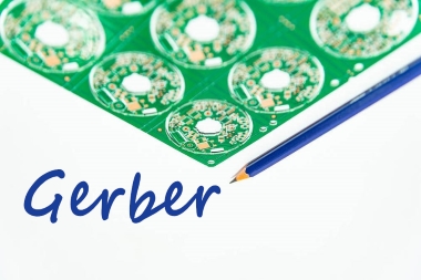
Common Issues with Gerber and Solutions

One thing that all printed circuit board and PCB designs have in common is their reliance on high quality Gerber files. It also known as the backbone of the electronics manufacturing industry. In the digital age, electronics are very important to many different fields. Therefore, efficient and powerful PCB Gerber files enable PCB manufacturing to be done better, faster and easier.

A Gerber file can be defined as a PCB blueprint in digital format for the layer-by-layer printed circuit boards fabrication. Moreever, it is also an input for the PCB manufacturer, guiding the manufacturing and fabrication process in detail.

To start with, PCB designers will design PCB boards using a special set of tools, mainly with CAD and EDA, which help generate basic PCB manufacturing data. Therefore PCB manufacturer will produce based on the data provided by the Gerber file. If the customer provides the PCB design files without include the Gerber file, then production will face many difficulties.

Avoiding Gerber file problems is critical to the execution of PCB manufacturing

The following are some of the most common Gerber file problems encountered by PCB manufacturers.

-The Gerber file is missing or incomplete

Sometimes, Gerber files created for the same PCB are not necessarily identical in size and specification. A missing detail can change the entire configuration of the PCB by changing the size, shape or position of the holes on the board.

-Empty files

Design errors can result in the creation of zero-byte Gerber files that do not contain information that can be used for PCB fabrication and manufacturing. Hence, it is important to check the validity of the Gerber file before sending it to the PCB manufacturer.

-Insufficient internal clearance

This refers to the minimum clearance required between the drilled holes and the adjacent inner layers of copper interconnected on the PCB. Insufficient internal clearance can cause a short circuit in the internal copper layer during the drilling process.

-Wrong laminate layer

-Missing solder resist layer

If you have a PCB with two or more layers, the file must have two solder resist layers. One for the top layer and the other for the bottom layer.

-PCB dimensions do not match

-Missing drill file

Ensure that the holes drilled in the PCB are accurately positioned and sized.

-Incorrect file labels

Each Gerber file needs to follow standard naming conventions so that the manufacturer can easily understand its expected use.

-Excessive list of hole sizes

The potential for errors increases when multiple aperture lists are generating for each layer in a format different from that of the Gerber file.

Methods to avoid Gerber file errors

As problems with Gerber files can have time-consuming and expensive consequences, here are some suggestions to help you avoid issues with Gerber files.

  1. Use a Gerber file viewer to check the Gerber file
  2. Make PCB samples to ensure correct specifications
  3. Use HD CAD software
  4. Follow QA practices. Ensure that Gerber files are checked for completeness, correctness and length and validity

If you order your PCBs from KingPCB, you don’t have to worry about errors caused by Gerber file issues. We carry out rigorous quality assurance, including Gerber file checks, to ensure you receive the highest quality printed circuit boards that perform at or above your expectations.

For proper advice or to share your requirements for the perfect PCB with a cost-effective strategy or to get a quote.

Categories
PCB Blog

Important Information About PCB Certification: UL, ISO, ITAR


When manufacturing PCBs, PCB manufacturers often face a situation where buyers who require UL certification, or ITAR registered suppliers or ISO PCB suppliers to work with. So, what exactly are these certifications means? Here are some useful tips on these commonly used terms.

UL PCB

For PCBs, the main standards are UL796 and UL94. The UL certification (Underwriters Laboratories) for flammability testing of all plastics to measure the long-term reliability and fire safety of PCBs. Furthermore, UL is a global independent safety science company with over 100 years of expertise in innovative safety solutions. Also UL recognition addresses component safety issues.

What does the UL Mark mean?

Hence, buyers of UL Recognized PCB products can be confident that the boards meet recognized component safety requirements. The base material complies with the flammability levels specified by UL94. For example, while FR4 required level is UL94 V0. This means that when a vertical sample of the material is introduced into the test flame and then removed, it will self-extinguish within 10 seconds. Therefore it will not drip out burning particles.

ISO PCB

ISO is the English acronym for an organization. The full name is International Organization for Standardization. ISO 9000 does not refer to a single standard, but is a collective term for a series of standards. ISO 9001 certifies that a company is manufacturing its products according to an appropriate and effective quality management. This system can evolve as it identifies possible areas for improvement.

ITAR Registration

Another important factor to consider when ordering PCBs is ITAR registration. It means that the product complies with the International Traffic in Arms Regulations (ITAR). The US government requires manufacturers and exporters of defense articles, services and related technical data to comply with these rules.

However, it does not mean that all suppliers registered with ITAR design their products for military applications. It implies that PCB assembly manufacturers of these products have appropriate processes in place to protect these items and technical data.

KingPCB Ltd

KingPCB is committed to providing customers with trusted printed circuit boards and PCB related products. When you order PCB products from KingPCB, you get products that meet global product safety and quality standards, so you can use them almost anywhere.

Contact us today for a quote on your PCB products!

Categories
PCB Blog

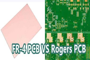
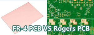
Find out which is better: FR-4 PCB V.S. Rogers PCB

In the world of electronics, the quality of PCB design affects the performance of the product and it is important to choose the correct and suitable PCB material.

PCB material, also mean substrate, is the dielectric board that holds the components and traces of the design. Basically, the materials commonly on offer in the market are FR-1 to FR-6, CEM1 to CEM5, insulating metal substrates, polytetrafluoroethylene (PTFE), polyimide, etc.

Among them, in this page we will discuss about the advantages of FR-4 PCB and Rogers PCB. To select your best choice of PCB materials types.

Why is FR-4 PCB the most commonly used type?

FR-4 PCB (printed circuit board) is a widely accessible and low-cost PCB. It delivers the advantage of “best performance” in various environments.

FR-4 glass epoxy resin is a popular and versatile high-pressure thermoset plastic laminate. Furthermore, it has a tremendous and excellent strength-to-weight ratio.

This material is well-known to maintain its high mechanical value and electrical insulating qualities under both dry and wet conditions. These properties, together with good manufacturing characteristics. Thus allows the grade to be used in a variety of electrical and mechanical applications.

What is Rogers PCB?

In most cases, a PCB consists of a FR4 composite material with glass fibre and epoxy resin.

PCBs using Rogers laminates refers to Rogers PCBs. Rogers is a company that produces laminates for the manufacture of PCBs that are designed primarily for high frequency and high-speed designs and have excellent dielectric constants and the ability to withstand high temperatures, making them suitable for use in the design and production of RF products and microwave equipment.

Rogers PCB V.S. FR-4 PCB, Find out which is better

The ultimate goal of any PCB manufacturer is to introduce cost-effective boards with the best performance. Here will be from the cost, impedance stability, thermal management, dissipation factor, moisture absorption, application and performance of the six differences between them.

  • Cost

Cost is a concern for many customers. FR-4 PCB is the most affordable in PCB manufacturing. If the design is for low frequencies and standard temperatures, the FR-4 PCB is the appropriate choice. While applies to high speed and extreme temperature use scenarios, then you can consider using Roger PCB.

  • Thermal management

PCBs generate a lot of heat in high-speed applications. Having good thermal properties is essential and in this case, the thermostatic laminates in Rogers PCB are the best choice.

  • Dissipation factor

It indicates the signal loss in the PCBs. The Rogers PCB has a much lower signal loss than the FR4 PCB, which has a dissipation factor of 0.02% compared to 0.004% for the Rogers PCB.

  • Impedance stability

The dielectric constant of the substrate is an important factor in determining the impedance of the board and its stability. The higher the dielectric constant, the higher the impedance stability. FR-4 PCB’s dielectric constant is 4.5, while Rogers PCB’s range from 6.5-11. Accordingly, high dielectric constant this characteristic makes Rogers PCB in high heat applications is an excellent choice.

  • Humidity absorption

This is directly relevant to the electrical and thermal properties of the substrate material. Rogers PCB material has very low water absorption and adapting to different environments.

  • Application and performance

FR4 PCBs are best for low and medium frequency applications. They are robust and have an excellent balance in terms of electrical stability. Conversely, Roger PCBs are suitable for high quality performance in niche areas such as space applications. Significantly, temperature constancy and low outgassing qualities make them the best choice for critical applications such as space and aerodynamics.

Turn to KingPCB for PCB manufacturing service:

At KingPCB, we combine state-of-the-art technology with our advanced engineering to provide you with the highest quality Rogers PCBs and FR4 PCBs. With over 10 years of experience in delivering high quality, on-time, competitively priced products, you can rely on us to meet your PCB requirements.

For an in-depth look at PCB manufacturing and PCB assembly services

Explore our PCB manufacturing services. In addition, you can contact us by email with any questions or to request a quote.


Categories
PCB Blog

How to Select Best PCB Board Material?

pcb material choose

Before learning about the PCB board materials we first know what is PCB. Also PCB is the Printed Circuit Board abbreviation. The main function is to support the circuit components.

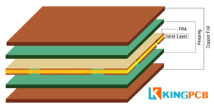
1. CCL

Copper Clad Laminate as a printed circuit board manufacturing substrate material. It is the electronic glass fabric or other reinforcing materials dipped in resin.

One or both sides covered with copper foil and heated and made of board material. CCL conducts, insulates and supports the interconnection of printed circuit boards. Copper laminate has a great impact on the transmission speed of signals in the circuit, energy loss, and characteristic resistance. Where copper foils are in multilayer board production, they are also available as cores.

CCL are divided into two categories, namely, rigid and flexible

2. Copper Foil

Copper foil is a cathodic electrolytic material. A thin, continuous metal foil deposit on the substrate layer of the circuit board acts as the conductor of the PCB.

The thickness of copper foil is normally in oz. 1 oz of copper is the thickness of copper foil spread evenly and flatly over a square foot area and is equal to 1.37 mil or 35 μm.

Common standards for copper foil are: 12μm (1/3oz), 18μm (Hoz), 35μm (1oz), and 70μm (2oz)

3. Preprag

Preprag is one of the main materials in the production of multilayer boards, consisting mainly of resin and reinforcing material, and multilayer printed boards use glass fiber as reinforcing material.

pcb board

The parameters of common PCB materials mean

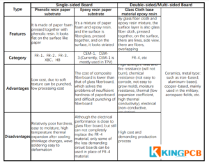
94HB: ordinary cardboard, not fire-resistant (the lowest grade material, die-punched, can not do the power board)

94V0: fire-retardant cardboard (die-punched)

22F: single-sided half glass fiber board (die-punched)

CEM-1: single-sided fiberglass board (must be computer-drilled, cannot be die-punched)

CEM-3: double-sided half glass fiber board (in addition to double-sided cardboard belongs to the lowest end of the double-sided board material)

FR-4: Double-sided fiberglass board

Halogen: contains fluorine, bromine, iodine, and other elements

Tg: glass transition temperature, i.e. melting point. The general TG is 130 degrees or more, high Tg is generally greater than 170 degrees, and medium Tg is about greater than 150 degrees

pcb material comparation

The main standards for substrate materials are as follows:

1. Chinese standards: China’s national standards for substrate materials are GB/T4721-47221992 and GB4723-4725-1992, and the standard for copper-clad foil boards in Taiwan, China, is the CNS standard, which is modeled on the Japanese JIS standard and was released in 1983.

2. International standards: JIS standard of Japan, ASTM, NEMA, MIL, IPC, ANSI, UL standard of USA, Bs standard of UK, DIN, VDE standard of Germany, NFC, UTE standard of France, CSA standard of Canada, AS standard of Australia, FOCT standard of former the Soviet Union, IEC standard of international, etc.

In addition, when selecting the best circuit board materials, KingPCB is an industry leader in quick turnkey PCB manufacturing. KingPCB offers rigid, flexible, and custom circuit board material options.

About KingPCB’s custom PCB manufacturing services

  1. Fast quotation within 24 hours
  2. Professional engineering team
  3. One-stop component sourcing service to reduce delivery time
  4. Perform multiple checks expecially during the assembly process to ensure the quality of prototyped PCBs
  5. Provide turnkey service from production to assembly

Contact us today to get more information and fast quotation soon.

Categories
PCB Blog

5 Tips Fast Track to be A PCB Assembly Expert

PCB assembly is the process of assembling all the electronic components together. People sometimes confuse PCB assembly and PCB manufacturing. There are two completely different concepts, PCB manufacturing covers PCB design, and PCB prototyping.

This article will describe the different PCB assembly techniques and processes to help you better understand the principles of PCB assembly.


Contents

  1. What is PCB?
  2. PCB Assembly Technology
  3. PCB Assembly Process
  4. How to Improve the Quality of PCB Assembly
  5. PCB Assembly -KingPCB’s Service


What is PCB?

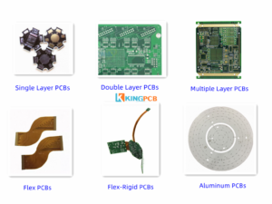
PCB is an abbreviation for printed circuit board. PCB’s primary function is to house electronic components and make electrical connections in the electronic components. PCB can be single-layer, double-layer or multi-layer. In 2014, the global bare PCB market exceeded $60.2 billion and expectingto reach $79 billion by 2024.


PCB Types


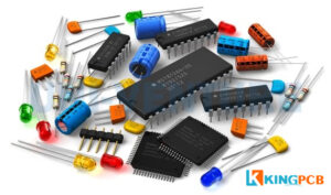
Main PCB Components

Diode: it allows current to flow in one direction

Lead: light-emitting diode that glows when current flows through it

Resistors: color-coded components that allow current to flow through

Capacitors: design to retain charge for device operation

Switches: allow or prevent the movement of current

Inductors: passive components that resist sudden changes in current

Battery: links voltage to the circuit


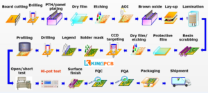
PCB Manufacturing Process

Single-sided process flow

Board cutting → dry film (line) → etching → CCD drilling → solder resist → character → molding → surface finish → electrical testing → final inspection → packaging and shipping

Double-sided process flow

Board cutting→ drilling → sinking copper → board electricity → dry film (line) → lamination → etching → two drilling (some ranked in the solder resist and surface treatment after) → solder resist → character → surface finish (sinking gold some ranked in the character before) → molding → electrical testing → final inspection → packaging shipments

Multi-layer process flow

Board cutting → inner line → browning → pressing → drilling → dross removal → copper sinking → board electricity → dry film (line) → graphic plating → etching → two drilling (some are ranked after anti-soldering and surface treatment) → anti-soldering → character → surface finish (some are ranked before gold sinking) → molding → electrical testing → final inspection → packaging and shipping

PCB Assembly Technology

SMT assembly technology

What is SMT assembly technology? SMT is a method for assembling electronic circuits boards in which components are mounted or placed directly on the top layer of a PCB. Compared to THT, components become smaller and placement of components on both sides of the board. It allowing smaller PCB components with higher circuit density. SMT is ideal for high automation, reducing labor costs, and greatly increasing productivity, and components can be mounted on carrier strips.

THT assembly technology

What is THT technology? THT is the insertion of components with tails or leads into drilled holes in the PCB, also known as feedthrough board assemblies. The leads are then soldered to pads on the bottom of the board, usually using a wave soldering process. THT mounting is very reliable because it creates a strong mechanical bond and the process is relatively mature. Compared to the SMT process, there are fewer variables that may cause solderable problems. The process can make bare boards more expensive due to additional drilling and the potential need to print on both sides of the PCB.

Hybrid PCB assembly

What is hybrid PCB assembly? As electronics tend to be smaller and more functional designs, this places higher demands on PCB assembly. It is challenging to assemble highly complex circuits in a limited space using only SMT or THT, combining SMT and THT technologies with appropriate adaptations to simplify soldering and assembly.


PCB assembly process

Solder paste printing: The first step is to apply solder paste to the board. The printed circuit board and solder stencil are held in place by a mechanical fixture, and the machine applies the paste to the stencil until it covers each opening area evenly.

Pick and Place: Using a mounter that automatically places surface mount components on the PCB. The machine picks up the PCBs with vacuum clamps and moves them to a pick and place station where the PCBs are. Then placed on the workstation and the SMD components are placed on top of the solder paste in the specified location.

Reflow: The circuit boards are transferred via conveyor to a large reflow oven. It heats the solder in the paste at high temperatures to melt the solder. When heating is complete, the board will pass through a series of ovens consisting of cooler heaters, which will help cool and cure the melted solder.

Check: The assembled board should tested functionally to check for bad connections. Common inspection methods include manual inspection, x-ray inspection, and automated optical inspection.

Through-hole component insertion: When the board assembling with other types of components, such as SMT or PTH, you need to use manual welding or wave soldering welding methods to insert PTH components.

Functional test: Functional test is the last step of PCB assembly to test the functionality of the PCBA. The test will simulate PCB operation and monitor the electrical characteristics of the PCB with power and analog signals passing through the PCB.


How to improve the quality of PCB assembly?

Choose proper component size: It is important to choose the correct package size for each component. It is advisable to choose a larger package. That is relatively easier to assemble the entire board again when disassembling and soldering the components.

Design reasonable component footprint: Component footprint is another key consideration for PCB assembly. Furthermore each package is created exactly according to the pad pattern specified in the data sheet for each integrated component.

Design suitable component spacing: Insufficient spacing between components caused by overheating, is one of the main causes of PCB failure. This situation is more obvious in some complex circuits. Redesign and manufacturing will be time-consuming and costly.

Ensure accuracy of the BOM: An error can lead to huge trouble, and manufacturers need to spend a lot of time identifying the problem. When there are new components or replacement, the client should  update the BOM sheet in time to ensure its accuracy and validity.

Use of marker points: For use as a point of Mark points are very important for PCB assembly, especially when it comes to close spacing of components.


PCB assembly – KingPCB’s services

KingPCB Limited provides complete PCB assembly services. Including PCB manufacturing, component procurement, and assembly. KingPCB’s uses the most advanced equipment, with years of experience and stable relationships with electronic component suppliers. We provide the most reliable and highest quality one-stop PCB assembly services to meet the different needs of our customers.

Categories
PCB Blog

Why Should We Optimize the BOM to Achieve Rapid PCB Prototyping?

When developing a new product, we think of rapid PCB prototyping, meaning production in as short a time as possible. Shortening the design and testing of a process that is suitable for small batch PCB prototyping services. In order to maintain a competitive edge, it is essential to bring your product to market as quickly as possible. When taking your product from design to production, communication between manufacturers, suppliers, engineers and designers needs to be consistent in order for the final product to be of high quality.


An important document when communicating with your manufacturer is the BOM sheet. An accurate BOM sheet will help your design to be manufactured quickly. To optimize your bill of materials for rapid PCB prototyping, consider the following.


Ensure detail

Keep your manufacturer fully understanded of your requirements. The rule to follow for a BOM sheet must be to be as detailed as possible! Make sure your communication with the manufacturer is accurate and detailed. Including the smallest details such as the maximum voltage on the capacitor to be clear and ensure that no ambiguity leads to problems in subsequent production.


Labels / Remarks

Remarks are an essential aspect of the bill of materials. For some of the part types required for your product, substitutes can be found as long as they meet a wide range of specifications. When certain parts are temporarily out of stock, you can make a note to use alternative materials for a specific part type.


Ensure real-time updates

Keep a close eye on these changes and confirm the latest form in a timely manner. You may want to keep track of the reasons for changes to the BOM sheet and the possible implications, you can keep different versions of the BOM sheet. Remember to always give your manufacturer the latest BOM sheet! This is vital!


Summary

Developing an accurate and detailed bill of materials is a very important step in the PCB manufacturing process. By optimizing your BOM, you can avoid errors, sometimes a small mistake can be costly! The BOM list also helps you to correctly forecast the manufacturing and time costs of PCB manufacturing, by communicating in detail with your manufacturer to ensure that the BOM list is accurate and efficient.


KingPCB provides high-quality and defect-free PCB prototype assembly and manufacturing to customer requirements. Visit us to find out more about our PCB prototyping services, contact us to stay in touch!

Categories
PCB Blog

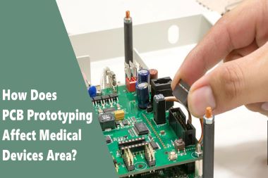
How Does PCB Prototyping Affect Medical Devices Area?

PCB prototyping is always valuable for about any electronics design application. However, the medical industry benefits greatly from rapid PCB prototyping in its development cycle.


Technical developers in the medical industry often use rapid PCB prototyping in their development cycles. So PCBs in this field are used for implantable medical devices, imaging devices and laboratory equipment used to diagnose and treat diseases.

Optimal functionality is critical. Prototyping allows designers to test the functionality of each PCB before it goes into production, thus ensuring that the PCB will function as needed. Rapid prototyping further improves the industry’s results by allowing for faster, more thorough testing.


PCB prototyping in implantable medical devices.

Cochlear implants – Hearing impaired people use cochlear implants to help hear sounds

Defibrillators – People at high risk for heart disease need implantable defibrillators

Reactive neurostimulators – used by people with epilepsy


PCB prototypes in medical imaging devices.

MRI

CT

Ultrasound devices


PCB prototypes in medical monitoring equipment.

Temperature monitor

Blood glucose monitor

Blood pressure monitors


Some other devices that also use PCB prototyping services are pacemakers, electromyography systems, peristaltic infusion techniques and muscle stimulation devices. Regardless of the type of device used, PCBs need to be created on a case-by-case basis to meet feature requirements or laboratory settings. For medical devices, SMT assembly works best.


For PCB prototyping, advantages of SMT include:

Easy to automate compared to through-hole methods

Lower Cost compared to through-hole

Takes up less space and is suitable for miniaturized devices


Guidelines for selecting a medical device manufacturer

For medical device manufacturers, strict FDA guidelines need to be followed, and it is critical for domestic and foreign manufacturers to register their facilities with the FDA. Companies need to register electronically, unless the FDA allows an exemption.


Another requirement that manufacturers need to comply with is the list of devices

Contract Manufacturer (CM)

Manufacturer

Contract sterilizers

Re-labelers and re-packagers

Remanufacturers

Specification Developers

Manufacturers of accessories and components for direct sales to end users

Decontamination machine disposable equipment

U.S. export only equipment manufacturers


Choose KingPCB as Your Medical PCB Prototyping Manufacturer!

In a word, choosing your electronics assembly partner is critical to any business, as PCBs can make or break the performance of any electronic product. However, when it comes to medical devices, the importance of reliable PCBs increases many times over. Therefore, partners must be chosen with the utmost care.


At KingPCB, we have over 10 years of experience in providing PCB assembly and manufacturing services. We use advanced production techniques and manufacturing practices to produce multi-layer PCBs with custom layouts. our competitive advantage comes from our ability to provide rapid prototyping and consistent, on-time delivery of quality products.


KingPCB guarantees:

Quick delivery

Accurate, reliable prototyping

Efficient and high-quality project completion

Reduced costs


Visit to learn more about our PCB prototyping services and feel free to contact us.