Categories
PCB Blog

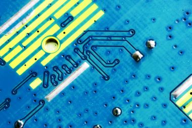
Copper-Filled Vias

Vias are the conduits that carry signals between PCB layers, without which the printed circuit board would not function.

During the PCB manufacturing process, manufacturers add a layer of copper to the board substrate to conduct electricity and connect each PCB layer. Keeping the through-hole intact, copper plating is used to transmit the signal. To increase capacity, another conductive material can also be used to fill the plated vias.

Manufacturers will use epoxy resin and copper to fill the vias to make their PCBs more suitable for certain applications, although the additional material will also increase the cost of PCB production.

This article will describe the main uses of copper-filled vias and how they can enhance your PCB.

Copper-Filling process

When filling vias with copper, it is important to form a uniform layer of copper in the through-hole, too thin and too thick copper layer will not work. If improper techniques are used, too much copper may be produced resulting in increased PCB weight or too much copper on the copper traces. The result can lead to the inability to produce PCBs that meet specifications, defects and increased costs.

A common method for manufacturers to fill copper vias is to use pure copper to fill the vias, however, this method often results in voids that trap contaminants in the middle, which later in the heating process will break the connection between the PCB copper layers of the vias.

What are the benefits of copper-filled vias?

Compared to boards with only copper-plated vias, PCBs with copper-filled vias have the following advantages.

Increased thermal conductivity: In applications involving high temperatures, the high thermal conductivity of copper attracts this heat away from the critical areas of the PCB.

Increased conductivity: The conductivity of copper allows high currents to pass through deeper layers without overloading the PCB.

Application of filled vias and copper plated vias

PCBs with copper-filled vias increase capacity, but correspondingly increase production costs. When you decide on a PCB via, you have to consider the heat and voltage intensity that the application will generate. In low-stress applications, PCBs with plated vias can work properly without defects. High power, RF, microwave, and LED applications can use PCBs with copper-filled vias, and the currents used in high-power integrated circuits for this type of PCB are suitable for copper-filled vias.

Choose a trusted board manufacturer that can effectively coordinate the creation of PCBs with copper-filled vias or other special requirements. Contact us now to learn how we can meet your PCB needs.

Categories
PCB Blog

How to Avoid Solder Balls to Get Perfect SMT Manufacturing

With the gradual development of electronic products toward lighter, thinner and smaller continuously. It has prompted more and more electronic products for different applications to adopt surface mount (SMT) technology.

In the SMT manufacturing process, the generation of solder beads has a great impact on electronic products, which can be caused by a variety of reasons and can eventually lead to PCBs failure. What exactly is a solder ball? This article will explain the causes of solder ball formation and how to avoid it.

What is a solder ball?

A solder ball is literally understood as a metal alloy ball formed on the surface of the PCB after welding. Solder ball mainly appears on the side of the SMD components or between the IC pins, if in the formation if not timely processing. It will not only affect the appearance of the product, but serious may also lead to short circuits in the process of use, and even harm the human body.

Some of the reasons for the formation of solder balls are

– High humidity

– Excessive flux in the solder paste

– Reflow process of high temperature or high pressure

– Improper cleaning

Best practices to prevent solder balls from forming

Ensure proper humidity

Too much moisture in the PCB will cause the generation of solder beads when the moisture expands dramatically to produce gas when it passes through the reflow oven after posting. Therefore, it is required that PCBs must be vacuum packed between putting into SMT production, and if there is moisture needs to be baked in an oven before use.

Select the right solder paste

The metal content of the solder paste, oxide content, metal powder particle size, solder paste activity, etc. all affects the formation of tin beads to varying degrees.

Preheat PCB

The higher the preheat temperature, the preheat zone is too rapid, it will increase the splash of gasification phenomenon, and the easier to form tin beads. Therefore, adjust the reflow oven temperature, reduce the conveyor belt speed, and take a more moderate preheating temperature and preheating speed to control the beads.

Solder resist

Ensure that the solder resists the layer in place and the correct use of solder paste so that there is no gap between the alignment and the pad. Use high-quality equipment while maintaining the board’s preheating speed.

Pad Spacing

Incorrectly placed pads not only lead to solder ball formation, but also to solder ball dislodgement and short circuits. Therefore, pads must be placed in an optimal manner.

Stencil

Stencil openings without anti-tin bead treatment, improper opening, too large, offset, or too thick can lead to tin bead generation. And clean stencil is also very important, clean stencil is not timely, or wipe incomplete, resulting in residual solder paste on the back of the stencil, and contamination of the PCB board surface, resulting in tin beads.

To sum up

In SMT production, there are many reasons for tin beads, only focus on one aspect or adjust a parameter is far from enough. It is necessary to control every detail at each stage of PCB production so that the soldering can achieve the best results and meet the high-quality requirements of electronic manufacturing technology.

It is important to choose the right electronic contract manufacturer, KingPCB has extensive manufacturing experience and strict quality control measures to provide high quality PCBs. we have more than 10 years of experience in SMT assembly, if you are looking for high quality SMT PCB solutions, you can contact us or via email to send your inquiry!

Categories
PCB Blog

Guidelines for Reducing PCB Costs

In order to reduce the total cost of PCB manufacturing, several key design factors need to be considered prior to the first build.

SMT and PTH

Surface mount technology (SMT) for PCB assembly is usually the least expensive and more mature process for manufacturing designs, reducing or removing all plated through-hole (PTH) components where possible.

PTH components are typically more robust than SMT components, making them ideal for connectors. PIH technology (Paste in hole) is a process where the plated through-hole in and around the PCB is. The PCB can be connected to both the hole and the SMT component after only one reflow process. PIH makes the processing of double-sided circuit boards easier and cheaper.

PIH requires two design prerequisites

Firstly, the insulation of the assembly must be able to withstand lead or lead-free reflow temperatures.

Secondly, the vertical and horizontal gaps around the leads must be large enough to allow a sufficient amount of printed solder paste.

For designs with relatively few components, use single-sided PCB SMT where possible to reduce assembly complexity. Avoiding rework of assemblies due to unnecessary complexity and component damage delays production volumes and increases costs.

Layout

The size of the PCB will directly affect its cost, the sizing determines the number of systems per panel. The dimensions of the layout should be as small as possible, taking into account the minimum number of layers within the PCB and for grounding. Blind holes buried within the PCB are often used to minimize the space impact on the top and bottom planes.

BOM components

Each component in the Bill of Materials (BOM) should provide unique value to the system. Check each component carefully to see if the system will not operate properly if a component is missing.

Tolerances 

Passive component suppliers segment their products by offering multiple tolerance ranges for capacitors, resistors, inductors, and others (e.g., 1%, 5%, 10%, and 20%). This helps them to sell the total capacity of their plants at the highest price the customer is willing to pay for the tolerance accuracy achieved by their manufacturing.

Power requirements and sizing

Passive components are rated according to their maximum power consumption, e.g., ¼ watt resistors. The maximum power requirement required for each passive component is assessed and only the required criteria are included in the BOM. This is usually also driven to the smallest size component.

Active circuit performance

The best systems may require the highest performing active components. When clock frequencies, switching speeds, signal-to-noise ratios, or high gain drive differentiation, there is no substitute for the highest performance semiconductors. However, for those applications where this is not the case, make sure the system is not ‘over-engineered’.

Memory size

Although memory is almost always available in 2n bit sizes, there is no extra value in unused empty memory. Compress firmware or compute memory as much as possible and use only the minimum memory size required by the system.

Purchase Quantities

Whether sourcing larger quantities of components internally or with your PCB turnkey solution, consider working closely with your system’s logistics planner. Once your system is in stable production at a proven operating rate, buying larger quantities may help reduce component pricing in the long run. Review component costs from as many distributors as possible to get the best pricing.

Since many designs go through multiple tests and debug iterations before they are ready for final production, the embedded test pattern circuitry in the first system design may no longer be valuable in production. Unless test points or debug circuits are required to observe behavior during or after production, consider removing test patterns or non-essential features from the production version of the system.

Packaging

Work with a trusted PCB Assembly factory to understand how component packaging formats can effectively reduce costs. While tape and reel are usually the most common packaging, some older, vintage analog components may still be supplied in tube format only. Larger and more complex semiconductors may also be available in tray format only. Understand the implications of these design and ordering trade-offs for your manufacturing facility.

Conclusion

Before handing over a new project to a PCB manufacturer for production, consider all the ways in which costs can be reduced during the design phase. There may be trade-offs between cost and performance that need to be appropriately discussed with the PCB design and manufacturing teams to ensure maximum efficiency and flexibility are achieved in the manufacturing process

Categories
PCB Blog

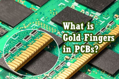
What Are the Gold Fingers Top Strategies in PCBs?

In many of today’s devices, the transmission of signals must be carried out between two or more circuit boards. Using a gold finger, a computer’s motherboard can quickly read the program of a circuit board. So, what exactly are Gold Fingers? How do they work inside computer technology?

What is a gold finger?

What we often refer to as gold fingers are the gold-plated posts seen on the edges of printed circuit boards, which are shaped like fingers. It makes contact with anywhere from a few to hundreds of contacts all over again.

The main purpose of a gold finger is to assist the PCB to connect to the motherboard of a computer and communicate with various other devices through digital signals, such as consumer smartphones, computer peripherals, watches, etc. Due to its excellent electrical conductivity, this alloy is used as a connection to the PCB.

There are two processes for PCB gold fingers

– Electroless Nickel Immersion Gold (ENIG): Easier to solder and more cost effective than electroplated gold. However, it is thinner, softer (usually 2-5u) and not suitable for board insertion and removal.

– Electroplated hard gold: this gold is solid, hard and thick (usually 30u), more suitable for PCB continuous use of the abrasive effect.

How to use gold fingers?

The use of gold fingers is extensive. In addition to electrical conductivity, gold is also used to protect the connection edges from wear and tear during use. For any given computer device, you can see many peripheral connections to the computer itself through the PCB gold fingers. common uses for PCB gold fingers are:

– Interconnection points

Auxiliary PCB through the slot (such as PCI, ISA, AGP) connected to the motherboard, gold fingers in the PCB and the computer to play a role in the transmission of signals to and from the role.

– Adapters

Gold fingers can provide many enhancements to a personal computer, such as sound cards, by inserting the auxiliary PCB vertically into the motherboard, it allows the computer to provide enhanced graphics and high-fidelity sound.

– External connections

The computer’s peripherals are connected to the motherboard through the PCB gold fingers.

Gold fingers provide the modular PCB with the ability to operate and provide modern functionality for users of remote and stationary computing devices. In addition to personal computers, PCB gold fingers are also used as connection points in computerized industrial machinery.

What are the specifications of gold fingers?

In the process of plating PCB gold fingers, the corresponding rules must be observed in order to make it work properly.

Plating through-hole should not be close to the gold finger

– Gold fingers should be kept at a certain distance from the solder resist or silkscreen, not to touch

– Gold fingers must face the opposite direction of the middle of the PCB

PCB gold finger advantages and standards

Due to its electrical conductivity and wear resistance, gold is considered to be the most suitable metal for connection contact, but the cost is also more expensive. Gold itself is relatively soft, in order to be more strength, gold used in printed circuit boards is usually combined with nickel or cobalt to form an alloy for use.

For plating processes, nickel thickness is typically between 150 and 200 micro inches.

The standard for the production of PCB gold fingers was established in 2002 by the Institute of Electronic Connectivity (IPC). Currently IPC A-600 and IPC-6010 are the most widely used standards.

– Chemical composition

In order to obtain the maximum rigidity of PCB contacts, the gold plating layer should contain 5%-10% cobalt.

– Thickness

The gold finger plating thickness should always be in the range of 2 to 50 micro inches. The standard thicknesses for delineation are 0.031 inch, 0.062 inch, 0.093 inch and 0.125 inch.

– Visual inspection

To test gold fingers through a magnifying glass.

– Tape test

To test the adhesion of the gold plating to the contact, a piece of tape is placed along the edge of the contact, and when the tape is removed, if there is visible gold plating on the tape, the plating lacks sufficient adhesion to the contact.

How does gold fingers change the world?

With more and more technologies relying on gold fingers, gold fingers have made the electronics industry more productive and capable than ever before.

To learn more about how KingPCB produces assembled gold finger PCBs, contact us today for more information and a quote!

Categories
PCB Blog

Standard Tests in PCB&PCBA

What types of standard tests are available in PCBs/PCBAs?

The inspection of PCBs & PCBAs is an essential step in order to ensure product quality. Today the PCB manufacturing industry and associated manufacturers have established a wide range of test methods and evaluation techniques that allow for better inspection of components that may have failed. Seven common inspection methods are as follows.

  1. Visual inspection, where the operator uses a magnifying glass or microscope to check if the board passes. Visual inspection is the most traditional method of inspection, but due to the increase in PCB production and the continuous development of high-precision PCBs, visual inspection has become unfeasible and needs to be instrumented.
  2. ICT (in-circuit tester) is a modern electronic enterprise necessary PCBA (printed circuit board assembly) test equipment, it can find 98% of the fault. The ICT Test is mainly a test probe that touches the test points from the PCB layout to detect open circuits, short circuits, and the soldering of all parts of the PCBA. With simple operation and fast and accurate fault location, it can significantly improve production efficiency and reduce maintenance costs.
  3. FICT, also known as Flying probe testing, replaces the pin bed with probes, using multiple motor-driven, fast-moving electrical probes to make contact with the pins of the device and make electrical measurements. A typical ICT may take 30 seconds to test a UUT, whereas a FICT may take 8-10 minutes.
  4. FCT (functional circuit test) generally refers specifically to testing after the PCBA has been powered up. This type of test is always carried out at the end of the manufacturing circuit board programme, using a functional tester to check that the finished PCB meets specifications. The tester is usually connected to the PCB via its test probe points or edge connectors and tested to prove that the PCB functions according to the design specifications. The test process is fully automated by computer and the results are reported without human intervention, ensuring efficiency and compliance
  5. BSTT (boundary-scan test technology) is widely used as a method of testing integrated circuit boards. The cell is placed in the leads from the silicon to the external pins and the status of the input and output pins of the IC chip is tested, as well as the internal operation of the chip and the lead level for the break and short faults.

The main difference in this type of test is that it is possible to check for circuit or wire faults simply by running a computer program.

It is very suitable where reliability is important and troubleshooting time is short.

  1. AOI (automated optical inspection) is a device based on optical principles to detect common defects encountered in soldering production. The defects are displayed/marked out for repair by the display or automatic signs
  2. AXI (automatic X-ray inspection) X-rays are non-destructive and have different penetration rates for different substances. AXI technology is now widely used for product inspection in industries such as lithium batteries, semiconductors, integrated circuits, and electronics manufacturing.

Why is it necessary for PCB Testing?

  1. Error identification: Helps to identify possible functional, manufacturability, or PCB design and PCB layout problems in the PCB, so that designers can make timely adjustments
  2. Time saving: PCB testing at an early stage helps to save time, and complete and thorough testing helps to quickly identify the cause of problems and shorten product delivery lead times
  3. Cost reduction: testing products in small assemblies prevents the production of defective products and ensures that problems occur before they are put into production.
  4. Reduced rework rates: helps to reduce the number of products that do not meet performance standards, increasing customer satisfaction and improving the company’s reputation.
Categories
PCB Blog

Conformal Coating for PCB Protection

Electronics are involved in every aspect of our lives. This means that these electronic connections may be exposed to various environmental hazards such as extreme temperatures, humidity and dust. To prevent the effects that the environment may have on PCBs, one precaution you can take is to use a PCB conformal coating during the manufacturing process.

What is conformal coating?

Conformal coatings are special polymeric film-forming products that protect boards, components and other electronic devices from adverse environmental conditions. These coatings “conform” to the irregularities inherent in the PCB structure and environment. They provide higher dielectric resistance, operational integrity, and protection against corrosive atmospheres, humidity, heat, fungus, and airborne contaminants such as dust and dirt.

What types of conformal coatings are available?

There are several options for coating technology and the best choice for your particular application should depend primarily on your necessary level of protection.

-Acrylic resins

-Epoxy resins

-Urethane (PU) resins (UR)

-Silicone resins (SR)

-Poly(paraxylene) C, D, N

-Amorphous fluoropolymers

-Fluorinated poly(paraxylene)

What is the best way to apply a conformal coating?

Once the coating type has been selected, the next question is how to apply it. This is generally based on the following variables.

  • Board design requirements, designs with connectors, solvent sensitive components and other issues that can influence your decision
  • Equipment requirements, if the coating is only occasionally required, it may not make sense to take up capital and floor space with additional equipment.
  • Quality requirements, mission critical electronics that require a high degree of repeatability and reliability often require more automated application methods.
  • Pre-coating treatments, some processes require masking or taping prior to coating to prevent the application of unwanted surfaces.
  • Production throughput requirements, necessary preparation, speed of the coating process, and how quickly the board can be processed after the coating process.

PCB conformal coating applications 

Common application methods are: manual brush coating, spray method, dipping and selective coating.

Manual Brush Coating

Manual brush coating is best suited for small batch PCB production, rework and repair. However, manually finished coatings tend to be thicker and less aesthetically pleasing.

Spray

The spray method will use an aerosol spray to apply the coating and is suitable for small production runs. However, using this method can be time consuming, as the spray will also cover areas that do not need to be coated.

Dipping

The dip method involves dipping the board into the coating solution and removing it, and is suitable for high-volume PCB production. This method is fast and accurate, and can completely penetrate the board and cover the entire assembly. This method requires masking and should only be used for boards that receive coating on both sides.

Selective Coating Method

This method uses an automated robotic nozzle to apply conformal coating to specific areas of the assembly and is suitable for high volume PCB production. The coating is applied quickly and accurately to the desired area without masking.

Find the right coating for your PCB

Choosing the right conformal coating for your PCB application, deciding which coating to use can be a challenge, and when working with your PCB manufacturer, you can find the best option for board coating.

Contact KingPCB for more information on coatings and quotation!

Categories
PCB Blog

A Guide to Lead and Lead-Free Solder in PCB Manufacturing

For years, PCB manufacturers have been facing industry challenges with the influx of new technologies, including miniaturization of PCBs, flexible printed circuits and the growing demand for green electronics. With the specified demand, PCBs are manufactured using non-toxic, environmentally friendly materials that reduce carbon emissions.

In this article we will discuss the differences between lead and lead-free solder and their applications.

What are lead and lead-free solder?

Leaded solder is an alloy made from lead and tin as the basic components. The use of lead in plumbing systems and water supply pipes connected to lead solder has been banned in the United States for many years. That is because of the harmful effects of lead on human health. Due to the use of lead in plumbing systems and the inhalation of dust and fumes produced by lead during soldering.

Since lead can affect people’s health and is also harmful to the environment, leaded solder is gradually being phased out

The lead-free solders we mentioned are alternatives to the traditional 60/40 and 63/37 SnPb solders. In 2006, the EU issued the RoHS (Restriction of Hazardous Substances) regulation.

Today’s lead-free solder formulations are based on the following common metals: copper, tin, silver, nickel, zinc, bismuth and antimony.

Comparison of leaded and lead-free solder pastes

The general soldering temperature depends on the alloy mixture and quality, the higher the tin content, the higher the melting point and the cost of the product. Leaded tin solder is much easier to use. Lead-free solder paste will melt at a higher temperature of approximately 422°F.

Leaded solder pastes, on the other hand, are harmful to humans and the environment, must be used only when permitted by regulatory agencies, and must be disposed of properly.

Factors to consider what kind of solder

Reducing or eliminating solder defects can effectively improve the reliability of circuit operation. In addition to this, other factors need to be considered.

-Temperature

-Vibration

-Tin whiskers

-Preheat time and capacity

-Operator skill level

Choosing the right formulation will play a role in improving the reliability of manufactured PCBs, and ideally, your partner should have extensive experience in RoHS material compliance.

Impact of different types of soldering

The choice of lead-free products for wave or through-hole soldering is based on the specific requirements or design parameters of the final assembly PCB. The choice of leaded and lead-free solder paste can also have an impact on the quality of the final product. The impact is minimized when the PCB manufacturer implements tightly controlled soldering parameters.

How to choose the right PCB manufacturer?

As the European and American markets gradually shift to lead-free soldering practices, many companies are following the EU’s RoHS regulations, which limit the use of lead in electronics.

Your PCB manufacturer should help you with all the RoHS material compliance issues that affect your electronic PCBs. For more information on other electronics manufacturing regulations that may affect your designs, send us your request via email and one of our experts will contact you immediately!

Categories
PCB Blog

HDI PCBs for Medical Electronic Devices

Today, more than ever, electronics engineers have a reason to use HDI PCBs. Over the past few decades, PCBs have tended to become smaller and smaller in size, which has shown to be a clear advantage in the medical industry. As technology continues to iterate, so do the needs of the medical industry, and the following will demonstrate the usefulness of HDI in the medical industry.

What is HDI PCB?

It is worth noting that HDI PCBs, with their advanced technology, are able to integrate a large amount of internal wiring. Thus, making them more compact. HDI technology reduces size without sacrificing performance and is widely used in precision instruments.

Technologies required for HDI PCBs.

Stacked micro via

Interleaved micro via

Continuous lamination

Buried vias

Plated through-hole

Laser drilling, etc.

Why are HDI PCBs important for medical technology?

Medical device PCB manufacturers have high requirements and HDI technology is the best technology available for production today. Medical devices involve a lot of precision design and high-speed transmission in HDI PCBs. HDI PCBs is ideal for medical devices, such as pacemakers that require small size and light weight where the response time of the device can be the difference between life and death. After all, medical care is about speed with life.

HDI PCBs are more challenging to design and manufacture, and more costly. For smaller boards and the need for better performance, designers need to fit more components in less space.

Limitations of HDI PCBs

Every technology has its limitations, and HDI PCB technology is no exception. For most medical device manufacturers, however, the biggest limiting factor for HDI technology is its manufacturing cost.

HDI PCBs are rapidly evolving and require specialized knowledge and advanced equipment to manufacture. It is no less difficult to manufacture due to their sophisticated design, requiring more time to build each board.

HDI manufacturing requires more care than standard PCBs, and choosing the right HDI board with the reliable manufacturing partner can give you a more efficient, higher quality board.

Contact KingPCB now for more information on HDI PCBs!

Categories
PCB Blog

Complete Guide to Flying Probe Testing

PCBs go through a complex series of processes from design to final production assembly. To ensure that your product has high quality, you may need to perform high-end testing before releasing your product.

Flying probe testing is arguably the more reliable method of PCB testing, choosing the right test and allowing your electronic contract manufacturer to succeed and reduce turnaround time.

What is flying probe testing?

Flying probe testing is a kind of standard for testing PCB builds. It is often compared to in-circuit testing (ICT).

Flying probe testing primarily tests for

Resistance

Capacitance

Inductance

Open

Short

Diode

More

Advantages of flying probe test?

  1. Low upfront investment

Flying probe testing is very accurate, with up to 99% accuracy. And the upfront investment of flying probe testing is lower than ICT testing.

  1. Flexibility

You may not need to consider the test to make design decisions. Flying probe testing is very flexible, in contrast to ICT testing, which requires you to design the PCB so that the test fixture can access the components. Once the program is created for your test, it’s ready to go. Future probe testing of your product will require only minor adjustments at most.

What are the disadvantages of flying probe testing?

Similar to most other tests, flying probe testing does not activate the circuit. Also, flying probe probes cannot check ball grid arrays (BGAs) because the probes require access points to connect the components.

We mentioned earlier that the upfront cost of flying probe testing is relatively low, and if it is for high volume PCBs orders, flying probe testing will no longer be applicable, and the speed of ICT may make it a better long-term investment.

What kind of projects are suitable for flying probe testing?

Flying probe testing is ideal for small volume PCBs builds. Small batches can be 50, 100, 200 boards. If it’s a high-volume PCB then ICT is better value for money. If you don’t plan to do functional testing after visual inspection, flying probe testing is a good choice.

What is the lead time for flying probe testing?

Flying probe test runs take about 5-1/2 minutes per board, but also depend on the specific size. For very large boards it may take more than 30 minutes, but this is also relatively uncommon. In fact, some very small boards have been tested in less than 45 seconds.

Are there different levels of flying probe testing?

The level of the flying probe test depends mainly on the number of connectors, there are up to 16 headers, 8 on the top and 8 on the bottom. These tests can be performed on LEDs with flat probes and tests, but they are also more costly.

Another important difference in flying probe testing is that different brands of machines use different file types. If a customer has a product made by another electronics manufacturer and later takes their design elsewhere, the customer needs to provide the ASCII file to the new contractor.

Customized Manufacturing

Flying probe testing is the most cost-effective way to meet low volume requirements. It is intending to replace in-circuit testing, however, it is not necessary to use only flying probes to test your PCBs.

If you are unsure whether to use flying probe testing or in-circuit testing for your project, please contact us now! KingPCB’s professional and fast response to assist you in better completing your PCB project!

Categories
PCB Blog

Ceramic PCB

When we think of ceramics, we think of fancy china, and ceramic appliances fill every aspect of our lives. It is worth noting that this material due to its good heat dissipation, insulation, current-carrying capacity and a series of advantages, making it widely used in the electronics industry. The most common applications of ceramic PCB are high-power power electronic modules, aviation equipment, military electronics and other industries.

What is ceramic PCB?

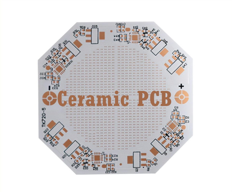
Ceramic PCB is bonded together by bonding copper foil and ceramic substrate under high temperature environment. With strong bonding, copper foil will not fall off, high reliability, stable performance in high temperature and humidity environment.

With the miniaturization of equipment becoming the norm, ceramic PCBs have been a good choice in many ways. Ceramic materials such as alumina, aluminum nitride, and beryllium oxide perform well on the following parameters.

  1. Thermal conductivity
  2. Corrosion resistance
  3. CTE component compatibility
  4. High density alignment, etc.

Advantages of ceramic PCBs

Here we need to remind you that the ceramic we mentioned is not a single material, but a class of materials with similar physical and chemical properties.

  1. Thermal conductivity. One of the major advantages of ceramic materials is the high thermal conductivity, heat can be easily transferred to the thermal landing or active cooling components. And the high thermal conductivity also ensures that no hot spots are formed on the surface and internal circuit layers because the heat transfer is uniform.
  2. Low conductivity. Despite the high thermal conductivity of ceramics, the electrical conductivity is low.
  3. High mechanical strength. It can withstand high mechanical loads as well as strong vibrations and shocks for long-term use in harsh operating environments.
  4. Strong bonding force. Ceramic PCB adopts bonding technology, copper foil is not easy to fall off.
  5. High current carrying capacity. 100A continuous current through 1mm0.3mm thick copper body, temperature rise of about 17 ℃; 100A continuous current through 2mm0.3mm thick copper body, temperature rise of only about 5 ℃.

Disadvantages of ceramic PCB

  1. Fragile. This is one of the main disadvantages of ceramic PCB, which leads to the production of only a small area of the board, and requires careful handling.
  2. Relatively high price. Ceramic PCBs are still used in some of the higher-end products, the use is not so widespread

Applications of ceramic PCBs

– High-power power electronic modules, solar panel components, etc.

– High frequency switching power supplies, solid state relays

– Automotive electronics, aerospace, military electronics

– High-power LED lighting products

– Communication antennas, automotive ignition

Turn to KingPCB for your ceramic PCBs project!

At KingPCB, our highly qualified and experienced PCB fabricators and assemblers fabricate ceramic circuit boards, not only single-sided, double-sided, and multi-layer PCBs, and we subject them to rigorous quality control testing to ensure that you get PCBs that are built to last, regardless of material, stiffness, or other customization factors.

To learn more about how KingPCB can meet all of your PCB needs, contact us today to get a quick, free PCB quote for your business.

Categories
PCB Blog

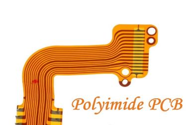
Polyimide PCB Characteristics and Applications

When we talk about printed circuit boards, there are many choices of PCB materials involved here, and what material is chosen depends on the environment in which it is applied. commonly used materials for PCBs are:
FR-4

Resin

Glass fiber cloth

Metal substrates

Polyimide, etc.

In this article, we will mainly introduce the main features of polyimide as a material and its application in PCB manufacturing.

What is polyimide?

Polyimide, PI, is a high-performance polymer with imide repeating units. As a special engineering material, polyimide has been widely used today in the fields of aviation, aerospace, microelectronics, nano, liquid crystal, separation film, laser, etc.

They can be classified into the following three types based on their chemical structures.

Aliphatic

Semi-aromatic

Aromatic polyimide

According to the thermal properties can be divided into

Thermoplastic

Thermosetting polyimide

Characteristics of polyimide PCB

Polyimide, a substance that exists naturally and can also be synthesized artificially, has the advantages of wide application temperature, chemical resistance, and high strength. These advantages make the application of PCB become more extensive and outstanding.

  1. Durability

The high resistance physical properties of polyimide enable it to maintain its shape even in harsh environments.

  1. Thermal Stability

Polyimide can withstand a wide range of temperatures up to 260°C

  1. Flexibility

The flexural strength of graphite or glass fiber reinforced polyimide can reach 345 MPa, and the flexural modulus reaches 20 GPa.

  1. Chemical resistance

The chemical properties of polyimide are stable. Polyimide does not need to add flame retardant to stop burning. Polyimide also has some chemical resistance, suitable for some applications where it is exposed to certain chemicals.

Applications of polyimide PCBs

Polyimide PCBs have a wealth of features that make them widely used in a variety of PCB industrial solutions: 1.

  1. Industrial equipment. Motor controllers, power inverters, etc.
  2. Automotive industry. Engine systems, brake systems, vehicle control systems, etc.
  3. Medical industry. Magnetic resonance imaging equipment, ultrasound equipment, etc.
  4. Military applications. Power distribution systems, defense navigation systems, flight instrumentation systems, microwave processing systems, etc.
  5. Telecommunications equipment. Signal towers, telephone switching systems, consumer electronics, etc.

Summary

The properties of polyimide PCB itself is a very good choice of PCB, polyimide PCB has good flexibility, thermal conductivity, quality and reliability. It is important to choose the right PCB manufacturer who can provide customized PCBs to meet your needs. KingPCB is committed to high quality, fast delivery, and competitive price PCB manufacturing services and has over 10 years of experience in this area.

You can send an email to sales@kingpcb.com get the information you want!

Categories
PCB Blog

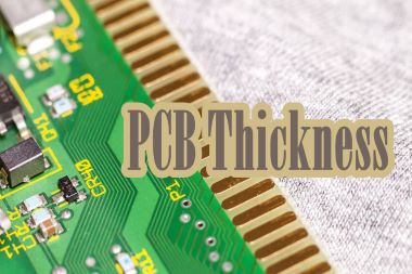
PCB Thickness

When we talk about the size of PCB manufacturing, the size of the standard provisions is essential. Although there is no specific standard for PCB thickness, but to maximize the convenience of PCB manufacturers to fabricate these PCBs, some dimensional standards have been used. For different needs of the PCB project, designers will design different PCB thickness. In this article, we will discuss how to determine the thickness of the PCB and some important factors affecting the thickness of the PCB.

What is the standard PCB thickness?

KingPCB commonly used board thickness is generally 1.6mm +/-10%, which is the most common PCB thickness in PCB manufacturing. Of course, there are other board thicknesses such as 0.8mm, 1.8mm, 2.0mm, etc.

To meet the needs of more robust or multilayer boards, the board may also have other thicknesses.

It is important to know the industry standard thickness, unconventional board thickness may require customization. The main factors that affect PCB thickness are design factors and manufacturing factors. We will detail these factors below and help you determine how to select PCB thickness for your project.

Design factors affecting the thickness of the PCB

  1. Size, weight and flexibility

For different needs, thinner boards are more flexible, but more likely to break due to brittleness. Thicker circuit boards are more robust, but they also take up more space within the device.

  1. Choice of board material

PCB operation and service life depends on the choice of materials, but these choices can also affect the thickness of the board. Circuit board manufacturing includes substrates, laminates, solder resist layers and screen printing. Substrates and laminates are the most important points to consider, as they greatly influence the overall thickness in construction.

  1. Copper thickness

Standard copper thickness in 1.4 ~ 2.8 mil, copper thickness depends on the need to pass the PCB current size, the thicker the copper, the thicker the board, the higher the cost.

  1. PCB layers

For 2 to 6 layers of PCB thickness may be within the standard board thickness, but for more than 6 layers of multi-layer PCB may require a greater thickness.

  1. Signal type

PCBs can carry a variety of signal types, high-powered signal boards require thicker copper and wider alignments, which means it will lead to an increase in board thickness. However, high-density boards with more complex signals often use laser micro via technology, finer alignments and high-performance materials, and they are usually thinner than other board types.

  1. Operating environment

The thickness of the board and the materials it consists of affect the conductivity and resistance of the PCB, so different thicknesses are required in different environments.

  1. Through-hole type

PCB through-hole through the board, which is important to create a more compact design. Many different through-hole types can be used.

Through-hole

Micro vias

Blind vias

Grounded

Solder pad vias

Manufacturing factors affecting PCB thickness

  1. Drilling equipment

When drilling any type of hole, manufacturers are limited by the thickness of the board and the diameter and depth capabilities of the milling machine and laser. For thicker boards, this means that manufacturers are less able to achieve small diameter holes.

  1. Copper thickness

Copper traces are completed by etching. The manufacturing process of etching or plating depends on the thickness of the internal copper layer.

  1. Layers counts

As mentioned earlier, the more layers on the PCB, the more difficult it is to manufacture to a standard thickness.

  1. Depanelization method

Manufacturers produce PCBs in large panels containing multiple boards, and then divide the panel into individual boards. The thickness of the circuit board affects the depaneling method that can be used-thicker boards may require careful depaneling using scores, while thinner boards may be routed to create separation labels.

Factors to consider when selecting PCB thickness

  1. Equipment capacity

When choosing PCB thickness, the first thing you should consider is whether your PCB manufacturer has the equipment to meet your specific needs, and of course, any more advanced technology will add a corresponding cost.

  1. Delivery time

For board thicknesses that require special customization may require the manufacturer to change the setup as well as the manufacturing process. The more difficult the requirement the further additional turnaround time will be added.

  1. Additional Costs

You should carefully communicate with your PCB manufacturer to assess the feasibility of your PCB project. Customization of PCBs with different parameters than the norm may result in different costs.

Contact KingPCB

Choose to work with a PCB manufacturer that can meet your needs and provide professional advice. KingPCB, a leading PCB supplier in Shenzhen, China with over 10 years of PCB and assembly experience. To learn more about KingPCB’s manufacturing capabilities, contact us today and feel free to ask any questions.