Categories
PCB Blog

Beware of These 8 PCB Layout Pitfalls

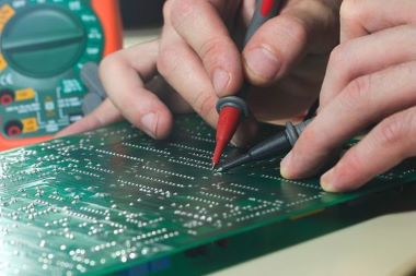
A printed circuit board layout consists of a number of copper traces and circuits that help establish connections between the components. How a PCB design and manufacturing occur largely determines how it will perform in the final product.

However, with the development of electronic technology, the circuit board is gradually in the direction of miniaturization and more precise development, so the layout will become more and more difficult and complex.

When designing PCBs, some layout problems can be costly and cause defects in the product, so they should be avoided whenever possible. Also, make sure you have a test strategy and involve your PCB suppliers early in the process to avoid design and manufacturing incompatibilities.

PCB layout traps

1. Plating holes/gaps

The holes and gaps in electroplating are caused by the imperfect deposition process. In the deposition process, if material contamination occurs, or contains bubbles, copper catalysis is insufficient, through hole cleaning is insufficient or rough drilling may cause electroplating hole problems.

Electroplating holes prevent current from flowing through the holes to the other side of the circuit board, causing the device to fail to operate properly.

2. Silver shavings

The solder shield or thin wedges of copper produced during etching, called silver chips, can affect the PCB’s function:

  • When long, thin layers of copper or solder resistance separate before they are fully dissolved in the chemical bath, silver shavings are created, which may attach to another board and cause a short circuit.
  • Fragmentation may occur when a part of the PCB is cut too thick or too thin. May cause corrosion of copper material over time.

3. Lack of solder layer between pads

When your PCB’s solder layer is partially or completely missing between pads, more copper than is needed will be found. This can result in welding Bridges forming between the pins when assembling the board.

4. PCB acute angle

An acute Angle in a circuit board generally refers to an acid trap, as it can capture acid during etching. The acid stays here longer than expected and can break the circuit connections, thus making the circuit defective.

5. Electromagnetism

Electromagnetic interference and electromagnetic compatibility are two of the most common problems with PCBs. This interference is usually caused by defects in the design process. Too much electromagnetic interference will cause the product to not work properly.

6. Insufficient spacing between copper edges

Placing copper too close to the edge of the board can cause a number of problems. If copper comes into contact with another conductive material, it may cause a short circuit; It is also susceptible to corrosion.

7. DFM

Manufacturability design is used to inspect circuit boards and solve problems that occur during assembly. If you don’t use DFM, it means that you may miss potential problems that can be fixed before the PCB is assembled.

8. Aging

Circuit board aging is the most common and unavoidable problem. As the board and its components age, they also become less stable, leading to PCB damage. The only thing you can do is replace the aging components or rebuild the circuit board.

Summarize

To avoid these possible board layout pitfalls, optimize your board layout, select the right components, and get your PCB manufacturer involved early, and conduct thorough early prototypes.

If you would like more information about PCB manufacturing and assembly, please contact us now and our experts will contact you quickly.

Categories
PCB Blog

PCBA for Aerospace Electronics

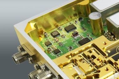
Advanced electronics are fundamental elements of the aerospace field, so you need to take extra care to ensure the PCB assembly efficiency of each electrical aerospace tool.

From standards to reliability, security in space-based systems must be achieved in nine out of ten cases. See this article to learn what you need to develop PCB assembly and design for avionics excellence.

Aerospace – Basic characteristics of PCB manufacturing and assembly

Unlike ordinary electronic PCBs, the development of avionics PCB manufacturing and assembly has strict requirements, any problems in the PCB will lead to aerospace landing problems. Therefore, it is necessary to make suitable and accurate PCB.

Circuit board design precautions

1. Material selection.

The manufacturing and assembly requirements for avionics are specific: if these electronics experience constant temperature fluctuations, early failure can result. It is best to choose low loss PCB material to reduce power loss. Circuit board materials should also meet CTE (coefficient of thermal expansion) conditions for high reliability applications.

2. Conformal coating.

The conformal coating on the circuit board acts as a protective barrier against corrosion, harsh environmental conditions and strong chemicals. A variety of coating materials can be used, such as acrylic, polyurethane, silicone, epoxy, etc.

3. Dissipate heat.

Heat dissipation means the transfer of heat by controlling thermal resistance (resistance to heat flow). The following points can help you establish good thermal conductivity.

  • Select components that meet aerospace manufacturing standards
  • Analyze temperature limits during the design phase
  • Through thermal analysis to ensure heat dissipation
  • Select panels according to space constraints

4. Compliance

Aerospace equipment manufacturing must take into account specific functions, appropriate process and component performance, which need to comply with the following standards.

  • AS9100: Aerospace Quality Management System
  • IPC 2220 series: Circuit board design and manufacture
  • IPC-A-600: indicates the circuit board acceptance requirements
  • IPC-J-STD-001 and Revision H: Welding requirements

5. Test after manufacturing

After the PCB is assembled and manufactured, testing is especially important to ensure the quality and proficiency of product delivery. You must first consider thermal testing. Vibration testing is another important test. In addition to internal tests like safety tests, quality tests are also checked.

Summarize

Hopefully, the guide given above will help you choose the best aerospace PCB assembly and design that meets all your expectations for your project.

KingPCB has more than 10 years of experience in various PCB solutions, such as consumer electronics, communications, industrial control, transportation, medical and other industries.

For any of your PCB related requirements, contact us now for a quick quote.

Categories
PCB Blog

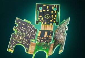
Rigid-flex PCBs Reduce Electronic Products Assembly Costs

Rigid-flex PCB fabrication may sound expensive, but they actually save a lot of money in the assembly of electronic systems.

Thanks to the Rigid-flex PCB structure, the circuit board can be bent and folded to reduce the size of the product.

What is rigid-flex PCBs?

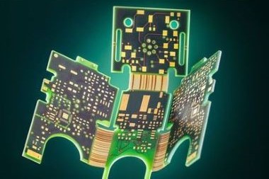
Rigid and flexible board is the combination of rigid PCB and flexible PCB technology. In this type of PCB, the subcircuits of a rigid PCB can be connected to one or more flexible circuits. The flexible part of a rigid flexible PCB is usually a multilayer printed circuit.

What material does rigid-flex PCBs choose?

Rigid-flex PCBs as the name suggests is a combination of rigid and flexible materials, including core, prepreg, copper foil, flexible laminates, cladding and bonding layers.

Flowless prepreg is one of the key components in rigid-flexible fabrication. This material prevents the epoxy from flowing into the flexible part of the PCB.

Flexible PCBs can be made of materials only a few microns thick and are commonly used in satellite and aerospace applications.

If you have questions about this, ask your PCB manufacturer for guidance on your PCB lamination and design rules.


How to reduce assembly cost with rigid-flexible PCBs?

Using rigid flexible PCB in your project can save some costs:

  • Direct cost: reduced bill of materials(BOM) and inventory. For multiple interconnected rigid PCBs, flexible PCBs can replace wiring harnesses and eliminate the requirement for connectors, providing direct cost savings.
  • Overhead costs: Because rigid flexible PCBs do not involve harness assembly, can reduce assembly costs and improve reliability.

How to minimize the manufacturing cost of rigid-flexible PCBs?

Keep the number of layers as few as possible

Reducing the number of layers can reduce the amount of prepreg for PCB manufacturing. The same fewer layers also simplify the PCB manufacturing process, thus reducing the total PCB manufacturing cost

Rigid laminates are used to achieve overall thickness

It is suggest to use rigid laminates to achieve a specific total thickness, which is less costly than non-flow prepreg.

Make sure the flexible part ends at the rigid part

If the PCB design requires one or more flexible arms of the flexible PCB to end in a flexible cable, additional mechanical support(flexible stiffeners). Because flexible connections do not have thickness or stiffness, having the flexible arm end up in the rigid part reduces the overall cost of a rigid-flexible PCB.

Summarize

The earlier you consult the PCB manufacturer in the planning stage, the better your PCB will be. Optimizing the PCB for your final product can save you money during system assembly.

KingPCB’s flexible PCB services include Flexible PCB prototype, Rigid Flexible PCB, and Flexible HDI PCB. Contact us now for the latest quote on your PCB!

Categories
PCB Blog

Bluetooth Circuit Board Optimization Design Guide

Bluetooth technology goes into a wide variety of electronics and devices. From headsets, audio products, and wireless electronics to home automation systems, the applications for Bluetooth technology continue to expand. When designing a PCB using Bluetooth technology, there are a number of challenges.

  • Signal integrity
  • Interference
  • Data loss, etc.

For the above problems, it is necessary to take some precautions.

Applications of Bluetooth technology

1. Audio/stereo products
2. Remote peripherals, such as game control or computer mouse/keyboard
3. Wireless electronic consumer products, such as cameras, printers, telephones
4. Large shopping mall beacons
5. Eddy current frames for industrial sensing applications, etc.

Bluetooth Circuit Board Optimization Design Guide

Because there are many sensitive components, they should handle carefully. Here are some design guidelines to follow regarding Bluetooth circuit boards.

Authentication Module

If Bluetooth is to be integrated into a product and resources are limited, consider using a pre-certified, fully included module to help speed development and time to market.

Check your Bluetooth device selection

Make sure you have the correct Bluetooth device for the application as well as the antennas are the right size and tuning. If you are going to use a simple beacon application, you can use low-power Bluetooth, but for higher throughput, you need something with more Tx power and faster data rates.

Separate or remove copper signals and high-energy components

Keep the antenna area free of any copper signals near the antenna area as well as high energy components (especially power paths that are switched through boost or buck converters). This also includes keeping the site (and board layers) free of planar and polygon dumping.

If you are going to arrange the antenna area manually, use ground planes appropriately to maintain good bandwidth at the input and make sure to leave enough space for tuning components (printed and ceramic antennas require ground planes).

Power supply considerations

It is essential to check that the rails supplying power to the Bluetooth module or chip are kept clean. You can also use ferrite beads on the power rails in the Bluetooth area of the board to suppress high-frequency noise.

Shielding strategies

Using EMI shielding strategies (such as increasing the distance between traces or adding EMI shielding) can ensure that high-frequency coupling does not interfere with components.

Physical size limitations

Most Bluetooth devices are portable and need to be placed in an enclosure, in addition to the board space limitations, as your device will also implement other functions.

Summary

Whether you are designing a small, simple Beacon module or a data streaming, power-hungry Bluetooth hub, following these considerations can save you a lot of trouble during your design’s test/implementation phase.

At KingPCB, we will follow the industry’s best practices for efficient, high-quality handling of your PCB manufacturing and assembly needs. Contact us now or send an email to sales@kingpcb.com

Categories
PCB Blog

How to Clean Printed Circuit Boards?

Printed circuit boards may be affected by various contaminants during use. To prevent circuit failure due to corrosion, cleaning after PCB soldering is necessary to ensure the reliability, electrical specifications and working life of electronic equipment.

How do I clean a printed circuit board?

Cleaning printed circuit boards is a very delicate process. When you work with printed circuit boards, you are dealing with a variety of exposed components and connections that can easily be damaged if you try to clean the board incorrectly.

How you will clean the printed circuit board depends greatly on the type of contaminants you are dealing with.

1. Clean the dust or dirt

Dust and dirt can easily get into a printed circuit board and render the device unusable, and there are several ways to deal with it.

  • Brushing. Use a small brush to carefully remove dust or dirt from the circuit board without damaging the components.
  • Compressed air. Compressed air is a common method for removing dirt and dust from electronic components, but there is a risk of damaging the connections.
  • Electronic component vacuums. These are special vacuums used by some manufacturers to clean electronic components.

2. Cleaning wet contaminants

  • Wet contaminants such as soda, dirt or oil can form a sticky film on the printed circuit board and also allow additional dust and dirt to adhere to it.
  • Isopropyl alcohol.

Using a cotton swab or small cotton tool, dip the swab into the alcohol and wipe over the contaminated part of the board to gently clean the PCB. It is worth noting to ensure that you are in a well-ventilated environment because of the possibility of toxic fumes.

  • Soften the water.

If you do not want to use alcohol or do not have access to alcohol, you can use softened water instead.

  • Specialized cleaners.

You can find PCB cleaners tailored to specific wet contaminants at many electronics wholesalers or retailers.

3. Clean up solder residue

PCBs always have varying degrees of flux residue and other types of contaminants on their surfaces after soldering, even with low solids, halogen-free, no-clean fluxes.

Removal of corrosion to ensure the smooth conduct of component electrical performance testing, excessive flux residues in the solder joint will make the test probe can not be good contact with the solder joint, thus affecting the correctness of the test results.

4. Ultrasonic PCB cleaning

Ultrasonic PCB cleaning is a universal cleaning method through the cavitation effect.

The machine will send high-frequency sound waves filled with cleaning solution in the tank, billions of tiny bubbles rupture, will be any contaminants from the printed circuit board blown away.

This method, however, can separate component end caps, loosen connections, and otherwise damage components.

KingPCB has clean, high-quality boards for all your applications

KingPCB, one of the industry’s leading suppliers, offers you a wide range of materials and high-quality printed circuit boards. For more information about PCBs, contact Kingpcb today or send emails to sales@kingpcb.com

Categories
PCB Blog

Nano Coating VS Conformal Coating, Advantages and Applications

Printed circuit boards (PCBs) are often damaged and corroded by dust, chemicals, pollution, humidity, and harsh environments. To protect PCBs from damage, a protective coating can be applied to the surface of the board to extend its life.

There are many types of protective coatings available on the market, the most common being nano-coatings and conformal coatings.

What is nano-coatings?

Nanotechnology is an interdisciplinary field that continues to foster a wide range of applications. In addition to building machines on a subatomic level, nanotechnology is also used as a protective coating.

Like conventional conformal coatings, nano-coatings protect PCB boards through their superhydrophobic properties, repelling liquid water and blocking moisture, thus preventing corrosive ions from being transported to the board surface.

Nanocoatings also have a number of special applications that are even more impressive than traditional coatings for aerospace, automotive, consumer, defense and medical applications

Applications for nano-coating

Not only do mobile phone circuit boards need to be protected from water, acid, alkali, and salt spray corrosion, but also from:

  • 3C electronics: headphones, computers, cameras, camcorders, game consoles, tape recorders, etc.
  • Marine and aviation industry
  • Printed circuit boards, PCB substrates,
  • Industrial controls
  • Micro motors
  • Capacitors
  • High gain antennas
  • Sensors, and other areas.

What is a conformal coating?

Conformal coating is the use of materials to coat the surface of a product to protect electronic components from harsh environments. The most common use is to protect against moisture. The number of industries where conformal coatings are often used is expanding, most notably medical, military, marine, automotive, and industrial.

Nano-coatings vs. conformal coatings

  • Nano-coatings are becoming a viable alternative to traditional conformal coatings for the protection of PCBs. This is particularly true for mobile electronics, including biomedical devices. In addition to being hydrophobic, nano-coatings can also repel oil (oleophobic) and have a low viscosity and solids content.
  • Nano-coatings are thinner and finer than classic coatings. They fit in well with biomedical concerns for personal safety and environmental protection, as they are gentler than solvent-based wet-applied coatings such as acrylics, epoxies, silicones, and polyurethanes.
  • Nanocoatings are easy to handle and can be formed in a single application. Like conformal coatings (acrylics, epoxies, silicones, polyurethanes), these conventional coatings are more viscous, need to be diluted for application, and are prone to unevenness.
  • Because they are based on nanotechnology, nano-coatings are stronger and lighter than most conformal coatings and better able to meet the specific requirements of limited microtechnology. This makes them a better choice for many biomedical technologies, especially for devices implanted in the human body.

To summarise

When choosing a coating for PCBs or other electronic devices, bear in mind the functional requirements of the application and the electronic device. Protecting the board is important, but using the right material is even more important.

If you would like to find out more about nano-coating or conformal coating, contact us now or send your emails at sales@kingpcb.com

Categories
PCB Blog

The Sequence Lamination PCB Technology and Trends

With the continuous progress of the times, the development of electronic technology has become more rapid and intelligent. Electronic devices are becoming smaller and smaller, and more and more sophisticated. Ordinary two-layer board may not be able to meet their needs, four-layer or more multi-layer PCBs gradually received attention.

For more than 4 layers of PCB will have the requirements of impedance and lamination structure.

What is sequential lamination PCB?

According to customer requirements, the process of rearranging the board into the physical configuration of the PCB is called PCB manufacturing. Sequential lamination is one of the steps in technical lamination, which is a method of adding layers of copper or some specific metal. For best results, each PCB board is subjected to at least two or more lamination processes.

Selection of sequential lamination structure

Before designing the PCB, we must first determine several parameters.

Board Thickness

For a relatively small area of the PCB, the thickness of the board is not so strict, but for a larger area of the PCB board, if the board is too thin, in the over the oven and over the wave soldering, it is easy to make the board deformed and concave in the middle. Therefore, we should consider this issue when choosing the thickness of the board.

Electrical Layer Order Selection

If we choose to put the CPU and DDR key signals in the top layer, and the DDR reference plane is preferably the GND layer, then our layer order should be TOP, GND, POWER, BOTTOM. Conversely, if we put the CPU and DDR key signals at the bottom layer, the order of the layers should be TOP, POWER, GND, BOTTOM.

Some challenges of sequential lamination

  • The limitation of the number of cycles.

In order to get a good lamination result, more than two cycles are needed. But that doesn’t mean it can be done any time you want. You must limit the number of cycles to two to four to prevent assembly defects.

  • Aspect Ratio

Aspect ratio is a measurement of the depth of the hole in terms of diameter. Depending on the type of equipment used in the drilling (beam drill or drill press), the ratio will vary and calculations will be based on it. The aspect ratio limits the layers used for different calculations in a multi-layer circuit.

  • Cost

Sequential lamination is a spontaneous build process that takes several days to build the required boards. Therefore, the more time it takes to develop the circuit, the more the cost increases gradually.

Advantages of sequential lamination

1. By using sequential lamination, the number of layers of the circuit is reduced
2. Maintains temperature with environmental changes
3. Reduces the mass of copper
4. Reduces the need for buried or blind vias
5. The structure of the circuit board is simplified, making it easy to handle

Conclusion

Sequential lamination provides multilayer stacking for PCBs, and despite some limitations, it is still one of the best processes for circuit board manufacturing. If you want an up-to-date, ready-to-use, modern PCB assembly circuit, PCB lamination technology would be a good choice for circuit design.

If you have any questions about PCB fabrication and assembly, contact us now or send emails to sales@kingpcb.com

Categories
PCB Blog

High Voltage PCB Materials and Design

Many applications require high voltage, from large industrial equipment to computers. Design standards have become more stringent as designers create PCBs for high voltage DC.

How to choose high voltage PCB materials?

The materials used in high-voltage PCB designs need to maintain optimal performance in both normal environments and overvoltage events.

To design components for high-voltage PCBs can consider the following factors.

PCBs materials

The basic PCB materials provide the basis for the rest of the components. High voltage is usually accompanied by high power, which means high current and high temperature. Therefore, you should choose a substrate material with a high coefficient of temperature expansion (CTE) and design for good heat dissipation and distribution.

So the board itself should be the first consideration when ordering materials. High-voltage laminates offer very high performance, but they are also very expensive.

Resin and glass

The resin and glass content of a circuit board affects its durability in high voltage situations. Boards with high resin content and small glass patterns provide the best dielectric properties.

Copper

For high current applications can adopted heavy copper PCBs design. And the copper used to create the PCB vias should be heavy enough to withstand high currents and mechanical stress.

High-voltage PCB design tips

Designers must carefully manage the power supply on the board to ensure power integrity to prevent accidental arcing between exposed conductors. These arcs can lead to component insulation damage or surface traces on the board, which increases the likelihood of future arcing. Eventually, arcing can cause a direct short circuit, and the resulting current surge can fry the board, damage components, or endanger users.

Therefore, after selecting the PCB material, design principles to improve its suitability for high-voltage DC bias need to be followed, such as

  • Selecting a smooth surface finish treatment and conformal coating to minimize the possibility of arcing.
  • Cutting slots or grooves in the board surface also helps to extend the creepage distance.
  • Keep power routing short, thick and as straight as possible.
  • Follow safety standards for spacing.
  • Avoid sharp corners in routing and pad layout
  • Reduce board edge burrs after routing

What are the high voltage applications?

Many industries require high-voltage resistant PCBs, such as

  • Spacecraft and other space equipment
  • High altitude vehicles
  • High-tech lasers
  • Particle colliders
  • Motor drives
  • Robotics
  • Computing devices

To summarize

Material selection for industrial boards is not limited to stacking options. While these are very important, the other materials listed above also play an important role in the ability of high voltage boards to operate reliably in an industrial environment.

The industry leader in beat automation, rapid, high quality prototyping and low volume production PCBs is experienced in building boards to meet the requirements of production facilities and will help you achieve your goals.

KingPCB has extensive manufacturing and assembly experience for PCB prototypes, low volume production, and high volume production. Contact us now for a quote instantly.

Categories
PCB Blog

How to Prevent Poor Solder Wetting?

Solder wetting defects generally means a kind of failure of the solder. The solder area of the circuit substrate (copper foil) or the external electrodes of the SMD to create a mutual reaction layer after wetting during the reflow soldering process, resulting in leakage or under-soldering.

By means of effective strategies, poor solder wetting can be prevented to ensure that your joints are durable.

What is solder wetting?

Solder technology is one of the oldest methods of permanently joining metals. Solder wetting is part of the process by which the metal in the solder is bonded to the metal on the printed circuit board (PCB) or component. During the wetting process, the solder becomes liquid and molten and adheres correctly to the component to obtain the best possible solder joint.

Wetting requires a copper surface that is free of contaminants and has reached the right temperature. Below, we will discuss why good solder wetting is essential.

Why good solder wetting is important?

Good solder wetting is essential for proper metal joining. Without it, the metal will not adhere correctly. Proper solder wetting will produce a good solder joint that will stand the test of time.

You can usually tell a good solder wetting by its appearance: a good solder wetting will be shiny and smooth with good flow. On the other hand, poor solder wetting is observable: its surface will look grainy, dull or porous and will result in poor adhesion to the component.

Causes of poor solder wetting

Poor solder wetting can be the result of a number of different problems.

  • Oxidation of the solder surface

If the solder tip is kept hot without a cover, it can react with oxygen and lead to improper wetting.

  • High or low soldering temperatures

Too high a temperature will cause the solder moisture to quickly turn into steam, too low a temperature and the solder will not flow as well as it needs to.

  • Excessive holding of the soldering iron tip

Holding the tip of the soldering iron on the component for a long time can lead to flux burn and component damage.

  • Insufficient wetting

Dirty boards or failure to heat the solder pads and pins can lead to insufficient wetting and poor bonding.

How to prevent poor solder wetting

  • Preheat the soldering iron

Prevent cold soldering by properly preheating the soldering iron with the power required to reach the optimum temperature.

  • Clean the surface

Clean any grease or dirt from the surface by wiping it with a common solvent.

  • Use a highly reactive solder paste

Highly reactive solder pastes usually provide better wetting and help prevent poor wetting during reflow.

  • Solder tips with solder

Adding solder to the hot end helps to prevent oxidation.

Contact KingPCB for the best PCBs

KingPCB has been specializing in the production and assembly of high-quality PCBs for over 15 years.

Contact us today if you have any questions. Or send emails to sales@kingpcb.com for latest quotation.

Categories
PCB Blog

Standard 4-Layer PCB Structure, Manufacturing and Cost

With the gradual development of electronic products to high-speed, high-capacity, multi-functional, miniaturization, the application of multilayer PCB becomes more and more common.

For PCB manufacturing, the more layers, the more manufacturing processes, the higher the corresponding cost. So multilayer PCBs are used more in advanced circuits. 4-layer PCBs are also widely used, this article will detail the structure, manufacturing and its cost.

What is a 4-layer PCB?

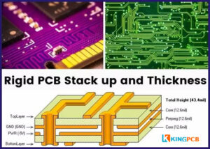
Four layers in a 4-layer pcb board is divided into two outer layers and two inner layers.

  • Signal layer (top layer)
  • Power layer (middle layer)
  • Ground layer (middle layer)
  • Signal layer (bottom layer)

Typically, the inner layer is used for power and GND, while the outer layer is used for signal routing as well as component placement.

4-Layer PCB Advantages

4-layer PCBs have more obvious advantages over single-layer PCBs, double-layer PCBs, such as

1. More components can be placed

2. Suitable for compact designs

3. Optimized signal routing

4. Better EMI shielding

5. Thermal control

Standard 4-layer PCB laminated structure design

A: Top layer (signal layer), Inner layer (power layer), Inner layer (ground layer), Bottom layer (signal layer)

B: Top layer (power layer), Inner layer (signal layer), Inner layer (signal layer), Bottom layer

C: Top layer (signal layer), Inner layer (ground layer), Inner layer (power layer), Bottom layer (signal layer)

4-layer PCB manufacturing process

  • Open material
  • Make L3 layer circuit
  • Press fit (L3 and L4 layer substrate with L2 layer copper skin press fit)
  • Drill L2-L4 layer blind hole
  • Copper plating
  • Resin plug hole
  • Copper reduction
  • Do L2 layer circuit
  • Pressing (L2-L4 layer and L1 layer copper skin pressed together)
  • Drilling
  • Plating
  • Outer layer circuit (do L1 and L4 layer circuit)
  • After process normal production

4-layer PCB cost

4-layer PCB and any kind of PCB are the same, there is no a standard cost, because many factors will affect the price. The main factors include.

  • Size
  • Material (different TG values require different prices)
  • Vias types and quantity (such as buried vias, buried vias)
  • Copper thickness
  • Surface treatment (normally is HASL, if you choose to ENIG then the price will increase)

Summary

The above is some knowledge about 4-layer PCB, if you want to know more about that, or get a quick quote on 4-layer PCB, contact us now or send an email to Sales@kingpcb.com

Categories
PCB Blog

Breadboard and PCB – What’s the Difference?

It goes without saying that printed circuit boards are important for electronic devices. PCBs carry various electronic components that provide circuit connections and various complex functions for different devices.

When you learn to create circuits as a beginner, a breadboard would be a good choice.

Breadboards, also known as prototype boards, are solderless boards with one or both sides. Since the board has many small jacks, various electronic components can be inserted or pulled out at will as needed.  Eliminating the need for soldering and saving time in circuit assembly, and the components can be reused, making it ideal for assembly, debugging and training of electronic circuits.

The common specifications of breadboard are 170 holes (35*47mm), 400 holes (85*55mm), 800 holes (165*55mm), etc.

Let’s look at some of the differences between PCB and breadboard

1. Application

Breadboard is suitable for the development stage and can change at will according to the demand. PCB is used for final electronic product integration, manufacturing and assembly according to Gerber files.

2. Components

One obvious difference between breadboard and PCB is that the components on the breadboard do not need to be soldered and can be changed instantly, so it is also called solderless breadboard. While the components on the PCB need to be soldered, such as SMT technology and PTH technology, so the PCB is also relatively more stable.

3. Capacity

There is no doubt that the load-bearing capacity of the PCB is significantly higher than that of the breadboard. Breadboard connects components through wires, so the current-carrying capacity is minimal. At the same time, PCB can also add a variety of components, but in the breadboard can not be completed.

4. Type

Breadboard is rigid, while PCB has a variety of options, it can be rigid, flexible, rigid-flexible combination to meet the needs of different scenarios.

5. Complexity

Even the simplest PCB has a much more complex structure than a breadboard. Usually breadboard consists of distribution bus and holes, PCB’s structure has at least substrate, copper layer, solder resist and screen printing.

6. Function

Breadboard supports components in a mechanical way, it does not perform electrical functions. PCB connects circuits in a mechanical and electrical way.

7. Appearance

The appearance of a breadboard is almost unchanging and relatively homogeneous. Whereas PCBs can be customized in various shapes, colors.

Choosing breadboards or PCBs?

If you are a circuit enthusiast or a beginner, breadboard can meet your needs. Breadboards can be easily prototyped and are relatively inexpensive. If you are looking for a long term, feature rich device, then a PCB is obviously the best choice.

Do you want to turn your breadboard prototype into a PCB?

After you have completed your development testing, you need to generate the Gerber files and Bom list for manufacturing your PCB.  Then send these files to a professional PCB manufacturer, such as KingPCB, and we will carefully review your files and provide a quick quote, and then you can produce and assemble your PCB.

If you have any questions or want to get more information about PCB manufacturing, contact us now or send emails at sales@kingpcb.com