Categories
PCB Blog

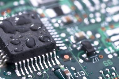
What is PCB OUTGASSING?

To ensure that defects are not created during production and use, PCB manufacturers outgassing printed circuit boards during production. Find out what can be done to prevent or reduce outgassing in this article.

What is PCB outgassing?

When outgassing occurs, the gases trapped in the PCB will release within the board in two common situations

During this process, any moisture near the through-hole is turned into vapour by the heat. When this gas escapes, it creates voids in the solder resist layer.

  • Use in ultra-high vacuum environments:

In applications involving ultra-high vacuum environments (such as outer space, laboratories or medical facilities), the vacuum can cause vapour to escape from the PCB, thus creating condensation in the rest of the device.

What are the consequences of PCB outgassing?

Both of these situations occur at different stages of the PCB lifecycle and so present a number of challenges to manufacturers, both of which can lead to defects in the PCB and therefore to a non-functional product.

When outgassing occurs during the soldering process, voids can form in the solder resist layer, which can lead to serious problems. During the deposition process, PCBs need to be drilled and copper plated, with a uniform layer of chemically plated copper acting as a conductor of electricity in the board. Outgassing of PCBs can lead to gaps in the copper plating, which can block the passage of current and cause defects and failures in the PCB.

The problem with outgassing in high vacuum environments depends on the equipment used. In space-related applications, outgassing forms condensate that can interfere with camera lenses or measuring tools, for example, causing problems with measurement results.

Medical facilities and scientific laboratories must have a sterile environment in order to use their equipment properly. Outgassing can contaminate equipment and the surrounding environment, posing a risk to patients or leading to inaccurate test results.

What are the available solutions?

Choosing the right materials

When choosing the materials that make up a PCB, plating made from gold, silver or tin may contain salts or organic substances which can generate gases when heated during the deposition process.

Correct manufacturing

To achieve a high quality PCB then the correct control of the manufacturing process is essential. When the chemical copper plating is too thin or the pre-heating process is incorrect, off-gassing usually occurs during the soldering process.

Even if the PCB has the right material and production method, it can still outgas in high vacuum applications. Baking PCBs for high vacuum systems during production is effective in reducing outgassing, especially when done in vacuum. The baking process removes any residual moisture before use.

Alternatively, when implementing PCBs, customers can design equipment to keep vapours away from critical components. Developing a path for the gas to escape through ventilation holes can prevent it from being trapped.

Choosing the right supplier ensures high quality PCBs

KingPCB is one of the leading PCB manufacturers in China and we have over 15 years of experience in manufacturing, assembly and sourcing of electronic components.

Choose to contact us for any assistance in finding the right PCB for you


Categories
PCB Blog

Common Errors and Solutions in SMT PCB Assembly

Surface mount technology is one of the most popular technologies and processes in the electronics assembly industry. When SMD assembly of printed circuit boards, SMT may lead to some PCB failures, reduce and avoid these defects to help improve the efficiency of PCB assembly services.

First of all, let’s review the knowledge related to SMT

What is surface mount technology?

Surface mount technology is a process of mounting electronic components directly onto the surface of a printed circuit board. The electronic components mounted in this way are called surface mount devices (SMD)

What are the advantages of surface mount technology?

Compared to PTH, SMT makes automation and higher density components on the board easier and allows for higher circuit speeds and better frequency performance.

What are the surface mount technology failures?

 Bridging

Solder bridging errors can lead to electrical shorts, which can cause circuits to malfunction.

  • Causes: The most commonly recognized causes make problems in the solder paste printing process, deviations in PCB pad configuration or stencil layout. Excessive solder paste deposition and solder paste cold collapse rate can also lead to bridging.
  • Solution: Select the proper solder paste metal to flux weight ratio, in other words, the solder paste will not collapse. Set the proper reflow profile, ensure point pressure and accuracy of component placement, etc.

Insufficient solder joints or electrical open circuits

When two electrical connection points are separated or the PCB breaks the circuit is called an electrical open circuit

  • Causes:Insufficient solder on the connector or solder paste blocking the holes of the stencil, or sufficient amount of solder paste, but in the reflow device does not contact with both the leads and pads
  • Solution: First, you can correct the stencil aspect ratio, the aspect ratio is too small may lead to solder paste blocking the hole. Also control the environmental conditions to avoid solder paste contamination.

Solder balls

Solder ball particles can form a false bridge between two adjacent leads, thus causing functional problems to the circuit.

  • Causes: One of the main causes of solder balls is when the solder paste is contaminated with moisture. Excessive oxides of solder powder in the solder paste will also form solder balls.
  • Solution: You can choose a coarser powder size

Tombstone

Tombstone defect is the component warped from the pad, or perpendicular to the board

  • Cause: It is caused by unbalanced force during reflow soldering. There is also uneven heating resulting in differences between component terminals.
  • Solution: The component body must cover at least 50% of the two pads to avoid unbalanced soldering forces. It is recommended to maintain a high preheat temperature so that the difference between the two ends during reflow is reduced.

Non-wetting or de-wetting

Non-wetting is defined as the inability of the molten solder to form a metallic bond with the base metal. The result is that the PCB pads or terminals of the assembly do not capture the solder during reflow.

De-wetting usually refers to alloy solder joints that do not extend to the PCB pads, so they do not get a good solder joint weld.

  • Causes: Poor PCB finish, too long soaking time during reflow, insufficient heat and other reasons.
  • Solution: Adjust the metal surface finish, such as higher temperature resistance OSP or ENIG. reduce the total analysis time before the reflow stage.

Solder beads

Solder beads are different from solder balls in that they are discrete.

  • Causes: Excessive solder paste; sometimes flux abandonment exceeds the coagulation force of solder paste during the preheat stage.
  • Solution: Reduce the thickness of the stencil or reduce the size of the aperture to reduce component pickup and placement pressure.

Insufficient filling or insufficient solder paste

The amount of solder paste deposits during printing is too small or there is insufficient solder after reflow to form round corners at the component leads.

  • Causes: Solder paste annual or metal content is too low; squeegee speed is too fast; stencil is sometimes clogged by dried paste, etc.
  • Solution: Clean the stencil regularly and control the speed of the scraper not too fast

Cold soldering or granular joints

PCBA solder end of the paste is not fully melting back to the phenomenon. For example, there are granular solder joints, the surface of the solder joint is not smooth irregular shape, or metal powder completely melted.

  • Causes: Reflow temperature is too low resulting in insufficient heat absorption of the solder, or reflow time is too short, or PCB pad cleaning is not sufficient and other reasons.
  • Solution: The maximum reflow temperature should be high enough; do not move the component during or after reflow; alloy analysis is necessary to check for the presence of contaminants.

Explore KingPCB’s SMT services

As PCBs miniaturize, more stringent and precise soldering control of the PCB assembly process is necessary. Reducing common errors in SMT is beneficial to improve SMT manufacturing efficiency.

KingPCB, as one of the leading PCB suppliers in China, has over 10 years of extensive manufacturing and assembly experience for your PCB project, contact us today for more information about our PCB services.