Categories
PCB Blog

Megtron6 Material Benefits and Applications

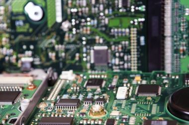
As electronic products become thinner and shorter, printed circuit boards have to move towards higher densities. Thin lines and small holes are a necessity, and the challenge is to increase transmission rates while maintaining signal integrity.

The lamination process for building multilayer circuit boards involves building up properties such as water resistance, reinforcement and protection, subjecting these layers to extreme pressures and temperatures to slowly cure, release and cool the material.

This article describes the unique benefits and applications of Megtron6 laminates, so read on to discover how they can enhance your products.

What is Megtron6 material?

Megtron6 is a popular high speed laminate material used in the manufacture of different types of PCBs. Designed for many different high frequency measurement instruments, integrated circuit (IC) testers and mainframes, Megtron6 has low transmission loss, thick layers and many different layers to enhance high speed networking equipment.

These laminates have electrical properties comparable to those of polytetrafluoroethylene (PTFE) materials, thanks to their high processability and unique advantages. In addition, they are compatible with lead-free soldering and can even prevent high-frequency signal reflections by means of thin foils for RF printed circuit boards.

Characteristics of Megtron6 materials

Low dielectric dissipation factor (DF)

Indicates the ability of a material to act as an insulating material or to retain energy. The lower the dissipation factor, the better and more efficient the insulator system will perform. megtron 6 has a low dissipation factor of 0.002.

Low dielectric constant (DK)

Ideal for power supplies and high frequency applications as they help to minimise power losses, Megtron 6 has a dielectric constant of 3.7 and virtually no current storage, making it ideal for such applications.

Low transmission loss

Some PCBs require low transmission loss materials to help reduce dielectric and conductor losses, which are necessary to achieve the demand for PCB materials.

High heat resistance

Due to its thermal characteristics, Megtron 6 laminates can withstand high temperatures.

Compliance with regulatory requirements

Megtron 6 laminates comply with the quality requirements and environmental regulations set by the Restriction of Hazardous Substances Directive (RoHS).

Through-hole reliability

Excellent through-hole reliability and resilience make it ideal for a wide range of niche applications.

Durability

Their strength allows the materials to hold up longer and remain useful so you can get the most out of them.

Thermal and electrical conductivity

Megtron 6 laminates are also excellent insulators. This material enhances the proper flow of electrical current while reducing leakage in both thermal and electrical applications.

Applications of Megtron 6 laminates

The following are the most suitable applications for Megtron laminates.

  • High frequency measurement equipment: providing accurate results.
  • High speed network equipment: helps to improve the operation of LAN and interconnect routing equipment.
  • High-speed mainframes: helps to improve the efficiency of equipment by maintaining the entire system and keeping it operating under optimal operating conditions.
  • High Speed IC Tester: The mechanical characteristics of the Megtron 6 laminate help the IC tester provide the most efficient and accurate results when testing other types of ICs.

Find your PCB solution with KingPCB

At KingPCB, we offer PCBs to suit your product usage technology. from rapid prototyping to high volume production boards, we work with a variety of industries including industrial, medical, aerospace, consumer electronics, automotive electronics and more. Our ability to deliver high quality and quickly, with competitive quotations sets us apart from the rest of the industry.

Choose KingPCB as your PCB supplier to realise your PCB project requirements. For any questions, welcome to contact us now.

Categories
PCB Blog

Which Works better? Thermal Pad vs. Thermal Paste?

With the miniaturization and intensification of electronic products, how to effectively dissipate heat has become a matter that PCB manufacturers need to face.

Thermal Analysis

Effective thermal management requires a detailed thermal analysis.

Thermal analysis assists designers in determining the electrical performance and reliability of components on the PCB, helping to determine whether components or PCBs will fail or burn out due to over-temperature function.

A simple thermal analysis simply calculates the average temperature of the PCB, while a complex one models the transients of electronic devices containing multiple PCBs and thousands of components.

PCB thermal management design practices

There are several thermal methods that can be used when designing and prototyping PCBs.

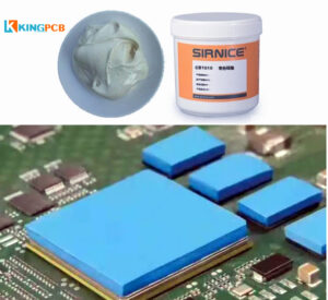
To ensure a good connection between the IC and the heat sink, thermal pads and thermal paste are often used.

What are thermal pads and paste?

Thermal pad

Thermally conductive pads are made of thermally conductive materials that are inherently sticky, soft, good compression properties, and excellent thermal conductivity. They help to dissipate heat easily when placed between the component and the heat sink.

What are the advantages of thermally conductive pads?

  • Easy deployment
  • Flexibility to cut to any size
  • Multiple material options

Thermal Paste

Essentially, thermal paste performs the same function as a thermal pad. The thermal paste works by closing any air gap between the heat generating component and the heat sink. This ensures that the air gap does not act as a thermal insulator and that heat is easily dissipated.

What are the advantages of thermal conductive paste?

  • Price advantage
  • Easy to apply, fills uneven gaps and provides a thinner interface, thus providing better thermal conductivity
  • Durable and more robust

Choose thermal pad or thermal paste? Which works better

The truth is that no one choice is absolutely perfect. Each material has its advantages and disadvantages, and the choice depends on the application requirements of the product. All we need to do is to carefully evaluate the thermal requirements of the board and then choose the most suitable material.

In addition to using thermal pads or thermal paste, you also need to use appropriate through-hole and surface mount pads, alignment wiring, and power layers for your IC design. This will greatly help you to manage the thermal condition of the board.

Explore KingPCB’s manufacturing services

In essence, thermal management is a technique used by PCB manufacturers.

KingPCB as one of the leading PCB manufacturers in China has over 10 years of experience. It is our goal to adhere to strict high standards of PCB manufacturing and assembly.

To get a fast PCB manufacturing quote, contact us now!

Categories
PCB Blog

PCB Basic Knowledge: PCB Core Materials and Prepreg Materials

We often refer to the PCB (printed circuit board) plays an important role in the electronics industry. PCBs build a bridge to the world of electronics, so to speak, and the core material and prepreg of PCBs assist in the construction of printed circuit boards.

In this article will take you to understand what is PCB core and Prepreg material, and the differences between them and the application.

What is Prepreg material?

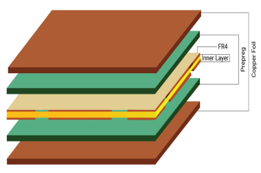
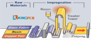
Simply put, Prepreg is a glass fiber with a resin binder impregnation. It is a dielectric material used to provide proper insulation between copper and PCB Core.

Prepreg is also commonly refers to as a bonding material that either combines two cores or a core and a copper foil. This plays a crucial role in PCB design and manufacturing.

The different types of prepreg depend on their thickness and the amount of resin they hold, the higher the resin they contain, the higher the price.

  • Standard resin (SR)
  • Medium resin (MR)
  • High resin (HR)

The process of manufacturing Prepreg

Why is Prepreg so important in the PCB manufacturing process?

  • Easy to apply
  • Facilitates waste management in the manufacturing process
  • Multiple Prepreg options available to meet different needs
  • Helps reduce the weight of equipment

What is a PCB core material?

A PCB core consists of a FR4 (flame retardant) rated glass fiber epoxy laminate with copper laminated on both sides. It is a rigid base material with copper laminated to the instrumentation used to manufacture single-sided, double-sided and multilayer circuit boards.

The difference between PCB core material and Prepreg material

Simply put, core material is the product of prepreg and lamination. As such, it is much more rigid compared to prepreg. Prepreg is partially dry without lamination and is not as rigid as core. The core consists of a glass fiber epoxy laminate which is flame retardant and has copper on both sides.

Another important difference between PCB prepreg and core is its dielectric constant. While the dielectric constant of the core does not change, the dielectric constant of the prepreg changes before and after lamination. The different dielectric constants are also a function of the following factors.

  • Resin content
  • Resin type
  • Glass braid

Explore KingPCB’s services

PCB cores and Prepreg are both important components of PCBs, and understanding these basics is critical to PCB manufacturing.

With over 10 years of combined experience in PCB manufacturing and assembly services, KingPCB offers advanced assembly technology and advanced PCB solutions. More than just high quality, we also offer the most competitive prices.

Don’t hesitate to contact us now to learn more about our PCB services

Categories
PCB Blog

PCB Temperature Guide

PCB temperature is an important indicator of safety, reliability and performance. Excessive temperatures are likely to cause failures and permanent damage.

During the PCB manufacturing process, there are several conditions that can generate more heat. For example, external component mounting, drilling and soldering processes, inadequate environmental ventilation and other factors can generate excessive heat, which can lead to damage to the board.

In either case, effective PCB cooling techniques and PCB thermal management can significantly control excessive PCB temperatures. In this article we will explain in detail there are issues related to PCB temperature.

How to measure the PCB temperature?

Before measuring the PCB temperature, you first need to determine the main heat source in the PCB, usually a microcontroller or processor, or locate the temperature sensor.

Next, find the connection to the ground (GND) pins of the heat source substrate. most of the heat generated in the PCB is transmitted to the temperature sensor through these pins.

Then we can start measuring the PCB temperature, which usually involves the following three steps.

  1. Place a grounding layer between the temperature sensor and the heat source
  2. Connect the GND pin of each temperature sensing to the ground layer of the heat source
  3. Ensure that the temperature sensor and the heat source on the PCB remain close to each other

Common causes of high PCB temperatures

How much heat a PCB can withstand depends on the materials used to make it up. Materials with the best thermal properties can effectively resist the effects of temperature. In the selection of materials for PCB, you can choose a high TG material.

Some common causes of high PCB temperatures are.

  1. Component failure.
  2. Through-hole interference.
  3. Surface mount component distance.
  4. High frequency circuits. 5.
  5. Lead-free solder.

Why is it important to measure PCB temperature?

It is important to monitor the PCB temperature, too high a temperature can led to structural changes in the performance of the PCB, or even damage.

Overheating in the PCB can lead to damage to the following.

– Structural integrity

– Circuit interruption

– Different material expansion rates

– Oxidation

How to prevent excessive PCB temperature?

To prevent the PCB from heating up, engineers can take the following PCB cooling techniques.

Use heat sink

Heat sink can effectively and safely dissipate heat.

Use a cooling fan

Cooling fan allows the temperature to dissipate while allowing cold air to enter, helping to prevent the PCB from overheating.

Select heat-resistant materials

Compared to standard PCBs, thick copper PCBs have excellent resistance to high temperatures and can handle higher levels of current and provide stronger connection points.

Increase the board thickness and width

In PCBs, thicker boards tend to be less efficient than thinner boards in terms of thermal conductivity, which means that more power is required to enable thicker boards to reach high temperatures, which can effectively avoid PCB overheating.

Application laminate

High-temperature PCB laminates can prevent overheating by providing thermal protection for PCB components.

Use similar coefficient of thermal expansion materials

The coefficient of thermal expansion (CTE) measures how much a material expands when exposed to high temperatures. In a PCB design, the ideal dielectric layer has a similar CTE to the copper layer. this way, if the layers expand, they will expand in a uniform manner, thus minimizing damage.

Maintain adequate spacing

When circuit board components are too close together, it may lead to crosstalk and increased alignment resistance, resulting in resistance loss and increased circuit heat.

Integrate heat pipes

The liquid in the PCB heat pipe piping absorbs heat and prevents it from damaging the board components.

Contact KingPCB

When you are looking for a PCB that can be specifically designed for temperature control, KingPCB is your trusted partner with extensive manufacturing and assembly experience to help you evaluate your project, and a professional team to help you manufacture your PCB efficiently.

Contact us today for a quote or for more information.